7 stopping procedures, Operation – MMD Equipment 400S-6B1 User Manual
Page 37
4. Operation
4-14
4.6.2 Meter and Indicator Lights while Operating
During normal operation, each indication of instruments is shown in the table below. Refer to the
table for daily checks.
Note; The values marked ※ vary with location of the voltage selector switch.
Monitor lamp
Indicator
lamp
Voltmeter
(V)
Frequency
meter
(Hz)
Ammeter
(A)
Oil
pressure
Water
temp.
Air filter
Turbo
protect
Diagnostic
Lamp
Glow
Before
Starting up
(preheatin
g)
0
0
0
●
Off
●
Off
●
Off
*
●
Off
●
Off
On
During
Operation
※
240
480
60
Less than
rated
current
●
Off
●
Off
Be sure to frequently check meters and indicators for
proper operation, or any machine water, oil, fuel leaks, etc.
The above table gives standard values. They may vary
slightly depending on operating conditions and other
factors.
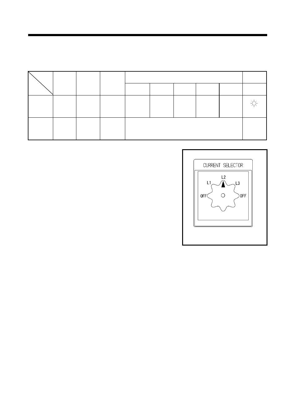
In single-phase load operation, check the current of L1, L2,
and L3 phase with the ammeter, by turning the ammeter
change-over switch.
Each current should be balanced if unbalanced. Change
load connections so the current of L1, L2, and L3 is equally
balanced. Make sure that the current of each phase does
not exceed the rated one.
Lamp marked * glows while low speed idling is kept for a
few seconds by ambient temperature. (See 4-2)
4.7 Stopping Procedures
<
Procedure>
①
Switch “OFF” the breaker on the operation panel of the generator.
②
After performing cooling down operation about 5 minutes, place the starter switch to the “STOP”
position to stop the engine.
③
While the machine is kept unused, keep the operation selector switch placed to the “OFF” position.
1
A080070
Ammeter change-over switch