0 measurement techniques and algorithms, Pinout, Figure 6: ring sensor pin out – Interlink Electronics Ring Sensor User Manual
Page 8: Figure 7: circuit schematic
www.interlinkelectronics.com
6
Ring Sensor
Integration Guide
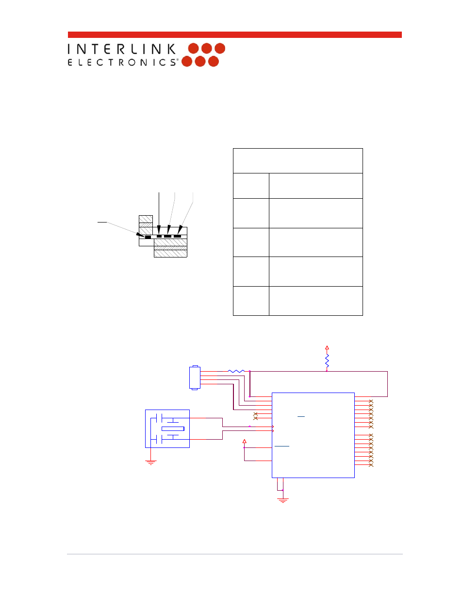
PINOUT
PIN #
REF
1
SENSE LINE (SL)
2
DRIVE LINE 1 (D1)
3
DRIVE LINE 2 (D2)
4
DRIVE LINE 3 (D3)
1
2 3 4
5.0 Measurement Techniques and Algorithms
The Interlink Electronics Ring Senor can measure radial position. The connection to the measuring
microprocessor is relatively simple and requires only a few external components.
Figure 6: Ring Sensor pin out.
MCLR
1
V
SS1
8
OSC1/CLKIN
9
OSC2/CLKOUT
10
RC0/T1OSO/T1CKI
11
RC1/T1OSI
12
RC2/CCP1
13
RC3/SCK/SCL
14
RC4/SDI/SDA
15
RC5/SDO
16
RC6/TX
17
RC7/RX
18
V
SS2
19
VDD
20
RB0/INT
21
RB1
22
RB2
23
RB3
24
RB4
25
RB5
26
RB6
27
RB7
28
RA0/AN0
2
RA1/AN1
3
RA2/AN2
4
RA3/AN3/VREF
5
RA4/TOCKI
6
RA5/AN4/SS
7
U1
PIC16F73
D3
D2
D1
Sense
R1
1K
VCC
VCC
R2
1M
2
1
3
X1
ResonatorWithCaps, 4MHz
1
2
3
4
J1
AVX #04-6227-004, or equiv alent
Figure 7: Circuit schematic.