Proof of purchase, Replacing damaged rotor blades, Replacing the balance-bar-to-upper-rotor connector – Interactive Toy Concepts Neptune User Manual
Page 2: Flying the neptune helicopter - smart control mode, Storing the neptune helicopter
Regardless of which Smart Control Device you are using, the basic operation of the Neptune Helicopter is the same. Follow
these easy instructions to connect your Neptune Helicopter and IR Dongle to your Smart Control Device.
IF APPLICABLE, ENABLE YOUR SMART CONTROL DEVICE’S AIRPLANE MODE WHENEVER YOU FLY THE
NEPTUNE HELICOPTER. IF AIRPLANE MODE IS NOT ENABLED, INCOMING CALLS ON THE SMART CONTROL DEVICE
WILL DISRUPT THE OPERATION OF YOUR NEPTUNE HELICOPTER AND MAY CAUSE IT TO CRASH!!
1. Install the IR Dongle into your Smart Control Device. The Connector on the IR Dongle fits neatly into the Headset Output
Jack on the Smart Control Device. The Green LED on the IR Dongle will flash whenever the left slider (throttle control) is
pushed upwards.
2. Turn up the volume on your Smart Control Device so that the IR Dongle receives a clear signal from the Headset Output
Jack.
IT IS INCORRECT TO TURN UP THE SMART CONTROL DEVICE'S VOLUME LEVEL BEFORE INSERTING THE IR
DONGLE. THE IR DONGLE MUST BE INSERTED FIRST. OTHERWISE, IF YOU TURN UP THE VOLUME BEFORE
INSERTING THE IR DONGLE, YOU WILL JUST BE TURNING UP THE VOLUME OF THE SPEAKERS / RINGTONES OF
YOUR SMART CONTROL DEVICE. IT IS NECESSARY TO TURN UP THE VOLUME ON THE HEADSET OUTPUT JACK
INSTEAD, AND FOR THAT IT IS NECESSARY TO HAVE THE IR DONGLE ALREADY PLUGGED IN.
3. Launch the NEPTUNE CONTROL App from your Smart Control Device.
4. Press the Options Button to access the Interface Options Screen. A description of the Interface Options Screen Follows:
-Under Band Options, select A, B, or C.
-Under Mode options select "Motion Control", or "Joystick Control". Motion Control uses your Smart Control Device's
accelerometer to allow tilting of the device to control the forward - backward direction, and left - right turning of the Neptune
Helicopter. Joystick Control uses an on-screen control pad to control the forward - backward direction, and left - right turning of
the Neptune Helicopter.
-Under Invert UI options, select one of the 2 arrows. This will change the orientation of the Control Screen, so that it
appears rotated 180 degrees on your Smart Control Device. The NEPTUNE CONTROL App appears on your Smart Control
Device in landscape view only. Both landscape view orientations are possible through 180 degrees of rotation.
-Press the Help Button to access additional connection information.
-Press the OK Button to exit the Interface Options Screen and return to the Control Screen. You are now ready to fly the
Neptune Helicopter.
5. Turn on the Neptune Helicopter.
TO FLY UP TO 3 NEPTUNE HELICOPTERS AT ONCE IN THE
SAME AREA, MAKE SURE TO TURN ON ONE HELICOPTER AT A
TIME AND CONNECT IT TO A BAND THAT IS DIFFERENT TO THE
ONE THAT IS ALREADY BEING USED. FOR EXAMPLE, WITH THE
FIRST IR DONGLE AND SMART CONTROL DEVICE, SET BAND A,
THEN TURN ON THE FIRST NEPTUNE HELICOPTER. THEN WITH
THE SECOND IR DONGLE AND SMART CONTROL DEVICE, SET
BAND B, THEN TURN ON THE SECOND NEPTUNE HELICOPTER
AND SO ON UNTIL ALL 3 BANDS ARE USED.
IF YOU LAUNCH THE NEPTUNE CONTROL APP BEFORE
INSTALLING THE IR DONGLE, THE "CONNECTION AND VOLUME
SCREEN" WILL APPEAR. WHEN THIS SCREEN APPEARS YOU
WILL SEE A CONNECTION ICON, VOLUME ICON, THE APP VOLUME SLIDER, A HELP BUTTON, AND A CONTINUE
BUTTON. A DESCRIPTION OF THE CONNECTION AND VOLUME SCREEN FOLLOWS:
-SINCE YOUR IR DONGLE IS NOT INSTALLED YET, AN "X" WILL APPEAR ON THE CONNECTION ICON. JUST
INSTALL THE IR DONGLE TO EXIT THE CONNECTION AND VOLUME SCREEN.
-IF YOUR VOLUME SLIDER IS NOT SET AT MAXIMUM LEVEL, AN "X" WILL APPEAR ON THE VOLUME ICON AND
THE SIGNAL LEADING FROM THE HEADSET OUTPUT JACK WILL BE WEAK. SLIDE THE VOLUME SLIDER ALL THE WAY
TO THE MAXIMUM (RIGHT) TO ESTABLISH THE STRONGEST SIGNAL. A "CHECKMARK" WILL APPEAR ON THE
VOLUME ICON.
-IF YOU NEED ADDITIONAL HELP WITH YOUR CONNECTION, PRESS THE HELP BUTTON.
-TO FLY YOUR NEPTUNE HELICOPTER, PRESS THE CONTINUE BUTTON.
This device complies with Part 15 of the FCC Rules. Operation is subject to the following two conditions:
1) This device may not cause harmful interference.
2) This device must accept any interference received including interference that may cause undesired operation.
Warning: Changes or modifications to this unit not expressly approved by the party responsible for compliance could void the user’s
authority to operate the equipment. The manufacturer is not responsible for any radio or TV interference caused by unauthorized
modifications to this equipment. Such modifications could void the user’s authority to operate the equipment. Note: This equipment has
been tested and found to comply with the limits for a class B digital device, pursuant to Part 15 of the FCC Rules. These Limits are
designed to provide reasonable protection against harmful interference in a residential installation. This generates, uses and can radiate
radio frequency energy and if not installed and used in accordance with the instructions, may cause harmful interference to radio
communications. However, there is no guarantee that interference will not occur in a particular installation. If this equipment does cause
harmful interference to radio or television reception, which can be determined by turn the equipment off and on, the user is encouraged to
try and correct the interference by one or more of the following measures: •Reorient or relocate the receiving antenna • Increase the
separation between the equipment and receiver • Connect the equipment to an outlet on a circuit different from that to which the receiver is
connected • Consult the dealer or an experienced radio/TV technician for help.
FCC NOTE: U.S. ONLY
Lithium Polymer Rechargeable
Batteries must be recycled or
disposed of properly.
Limited 30-day warranty
Product is warranted by Interactive Toy Concepts Limited against manufacturing
defects in material and workmanship under normal use for thirty (30) days from
the date of purchase.
Warranty is validated upon receipt of proof or purchase and
confirmation of UPC code.
Proof of Purchase
This radiocommunication device complies with all the requirements and limits of Industry Canada Standard RSS-310.
Operation is subject to the following two conditions: 1) This device may not cause harmful interference.
2) This device must accept any interference received, including interference that may cause undesired operation. Field Strength
and measurement distance: 27.145MHz – 61.35 dBµV/m at 3 meter. 49.860MHz - 59.69 dBµV/m at 3 meter.
Industry Canada Notice: Canada only.
INS-22005-130516-US
BladeRunner is a registered trademark of Interactive Toy Concepts Ltd.
© 2013 All Rights Reserved.
Neptune is a trademark of Interactive Toy Concepts Ltd. © 2013.
*IPhone, iPod Touch, iPad, Apple,
and Apple App Store are trademarks of Apple Computer Inc.
**Android and Google Play are Trademarks of Google Inc.
Manufactured by and distributed by Interactive Toy Concepts Ltd.
Conforms to Safety Standards ASTM F963-03 Regulatory Requirements.
Products and colors may vary. MADE IN CHINA.
In the event that your main Rotor Blades or Tail Rotor sustain damage, they are very easy to replace by following these easy
steps. (Note, replacement Main Rotor Blades are not included, but can be purchased separately as part of the Neptune
Replacement Part Kit.) (Note, 1 replacement Tail Rotor is included, and additional Tail Rotors can be purchased as part of the
Neptune Replacement Kit.)
Main Rotor Blades:
1. Locate the broken Rotor Blade and use a fine Philips screw-driver (not included) to unscrew the tiny screw that holds the
Rotor Blade in place on the Hub Mount. Be careful not to lose the screw as it is tiny.
REPLACING DAMAGED ROTOR BLADES
There are two small Connectors which connect the Upper Rotor to the Balance Bar. In the
event that a Connector becomes disconnected, broken, or lost, it will need to be reconnected or
replaced. Two replacement Balance-Bar-To-Upper-Rotor Connectors are included with the
Neptune Helicopter.
1. A Connector is attached by 2 simple Ball Joints. Remove the broken Connector by discon-
necting it from the Upper Rotor Hub Mount and the Balance Bar and pull it away. Once
removed, the Ball Joints will be exposed. A Ball Joint will be visible on the Upper Rotor Hub
Mount, and a Ball Joint will be visible on the Balance Bar. There are a total of 4 Ball Joints for
the two Connectors!
2. Install the new Connector following the reverse of step 1. Each Connector only connects to
2 Ball Joints. The Connector must connect a set of Ball Joints that are in vertical alignment
only. Gently but firmly press the Connector into position, connecting the Upper Rotor and the
Balance Bar. The Connector will just snap into the 2 Ball Joints as shown.
REPLACING THE BALANCE-BAR-TO-UPPER-ROTOR CONNECTOR:
This DEVICE(s) (Neptune Helicopter and the IR Dongle) is a precision machine and is factory assembled and tested. Keep this
DEVICE away from face, eyes and hair at all times. Keep fingers away from moving rotors or propellers. Do not operate this device
near or at other people or animals. Use caution when operate. Make sure people around you know that you are operating this
DEVICE. Recommended for use indoors only in rooms without obstacles, breakable objects or fans. The CHARGER and/or
charging cable provided in this package is for charging this DEVICE ONLY. Do not use any other source to charge this DEVICE. Do
not attempt to overcharge this DEVICE. Follow the charging instructions provided in this Instruction Manual. The Lithium Polymer
Rechargeable batteries in the DEVICE are sealed inside and are not replaceable; any attempts to replace the Lithium Polymer
Rechargeable Battery will void the warranty. The packaging should be kept since it contains important information.
IMPORTANT SAFETY INFORMATION
Web site:
www.interactivetoy.com
PLEASE! DO NOT RETURN THIS PRODUCT TO ANY RETAIL STORE!
For any questions or problems with this product please contact us at: Email: [email protected]
Phone: Inside North America: 1-866-214-2220 Outside North America: +1-416-444-6873
Address: Interactive Toy Concepts, 17 Vulcan Street, Toronto, Ontario, Canada. M9W 1L3
FLYING THE NEPTUNE HELICOPTER - SMART CONTROL MODE: - Continued
-Push the Control Pad to the left to steer the Neptune Helicopter to the left.
-Push the Control Pad to the right to steer the Neptune Helicopter to the right.
DIRECTION CONTROL CONVENTION IS BASED AS IF YOU WERE SITTING IN THE PILOT'S SEAT OF THE
NEPTUNE HELICOPTER. WHEN THE HELICOPTER IS FLYING TOWARDS YOU, THE STEERING WILL APPEAR TO
REVERSE. WHEN YOU PUSH THE CONTROL PAD TO THE RIGHT, THE NEPTUNE HELICOPTER WILL TURN TO THE
LEFT. WHEN YOU PUSH THE CONTROL PAD TO THE LEFT, THE NEPTUNE HELICOPTER WILL TURN TO THE RIGHT.
THIS PHENOMENON IS CALLED CONTROL REVERSAL AND IT IS NORMAL. IT JUST TAKES SOME PRACTICE TO
CONTROL.
7. a) In Motion Control Mode, forward and reverse control of your Neptune Helicopter is accomplished by tilting your Smart
Control Device forward and backward.
-Tilt the Smart Control Device forward to make the Neptune Helicopter fly forward or increase forward speed.
-Tilt the Smart Control Device backward to make the Neptune Helicopter fly backwards.
7. b) In Control Mode, forward and reverse control of your Neptune Helicopter is accomplished by pushing the Control Pad (on
the right side of the Control Screen) up and down.
-Push the Control Pad up to make the Neptune Helicopter fly forward or increase forward speed.
-Push the Control Pad down to make the Neptune Helicopter fly backwards.
8. These are the fundamentals of flying your Neptune Helicopter in Smart Control Mode.
THE CONTROL RANGE IS UP TO ABOUT 16' (5 METERS)
YOU CAN TURN THE FRONTAL RED LED ON THE NEPTUNE HELICOPTER ON AND OFF BY SIMPLY PRESSING
THE LIGHT BUTTON ON THE CONTROL SCREEN.
9. a) To land your Neptune Helicopter, gently and gradually push the Left Stick all the way down. This will slow the rotation of the
Main Rotors and the Neptune Helicopter will land. It is very important to NOT push the Left Stick all the way down suddenly, as
the Main Rotors will stop spinning instantly and the Neptune Helicopter will fall and possibly sustain damage.
9. b) Alternatively, to land your Neptune Helicopter, press the Emergency Stop Button on the Control Screen. This will bring the
Neptune Helicopter down gently.
10. a). To fly again, it may or may not be necessary to recharge your Neptune Helicopter, depending on the charge that is
remaining in the Neptune Helicopter’s Internal Lithium-Polymer Battery. Simply follow the steps described in the “CHARGING
THE NEPTUNE HELICOPTER” section above, to recharge your Neptune Helicopter. It may also be necessary to recharge your
IR Dongle. Just follow the steps outlined in the section "CHARGING THE IR DONGLE".
10. b). If you are finished playing, slide the Neptune Helicopter’s On / Off Switch to the Off position to turn it off. Then turn off
the NEPTUNE CONTROL App and remove the IR Dongle from the Smart Control Device.
THE IR DONGLE USES A SAFE INFRARED BEAM TO COMMUNICATE FLIGHT INSTRUCTIONS TO THE NEPTUNE
HELICOPTER. AN INFRARED BEAM IS VERY SIMILAR TO A BEAM OF LIGHT SO IT IS IMPORTANT TO STAY IN VISUAL
RANGE OF THE NEPTUNE HELICOPTER AT ALL TIMES DURING FLIGHT OR CONTROL WILL BE LOST.
TROUBLESHOOTING - If additional Rotor Blades or Connectors are required or if replacement does not solve the your
flying problem, visit www.interactivetoy.com. There is a vast list of Troubleshooting tips for the BladeRunner Neptune on our
website.nector will just snap into the 2 Ball Joints as shown.
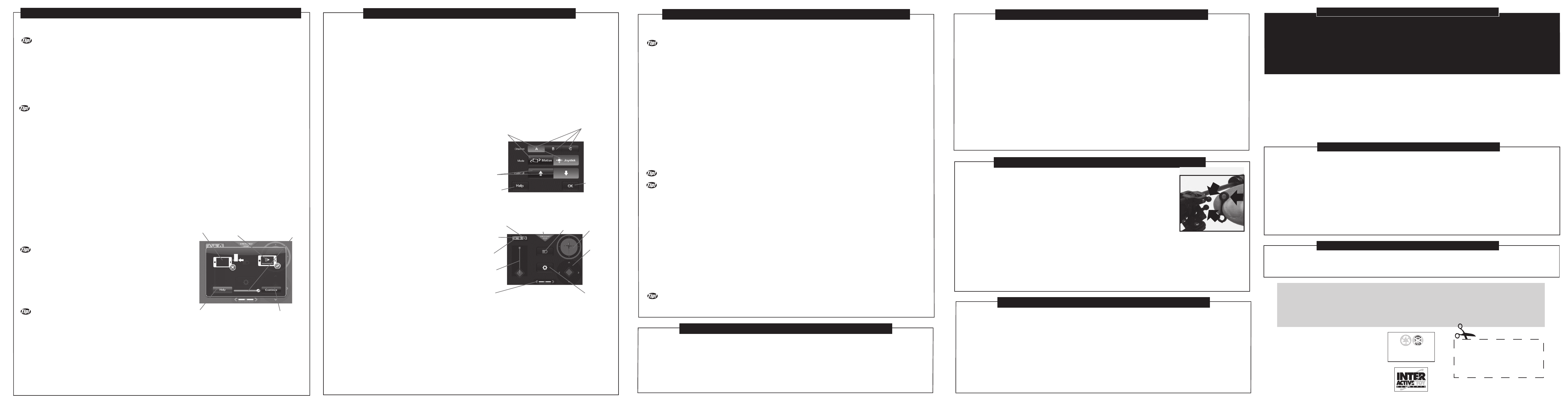
CONNECTING AND SETTING UP THE NEPTUNE HELICOPTER SYSTEM: -Continued
CONNECTION AND
VOLUME SCREEN
CONNECTION
ICON
VOLUME
ICON
HELP
BUTTON
CONTINUE
BUTTON
VOLUME
SLIDER
WARNING:
Check the condition of all the Rotor Blades prior to each flight. Do not try to operate the Neptune Helicopter if any Rotor
Blade has been damaged. Broken or damaged Rotor Blades may have sharp edges or corners and they will be spinning
fast with a potential for injury! Flying the Neptune Helicopter with broken Rotor Blades can also make it fly in an
unstable or uncontrollable manner. This may cause damage to furniture and other property, as well as injury to plants,
animals and people. Broken Rotor Blades can be easily replaced as described in the “REPLACING DAMAGED ROTOR
BLADES” section elsewhere in this Instruction Manual.
1. Slide the On / Off Switch at the bottom of your Neptune Helicopter to the On position. The Frontal Red LED on the
Neptune Helicopter will turn on and flash on and off for about 5 seconds. This will allow the Neptune Helicopter’s Gyro
to initialize.
2. Position the Neptune Helicopter on a safe, sturdy, and level launching surface. The Frontal Red LED on the Neptune
Helicopter will now light up continuously.
3. Push the Left Slider all the way up and then back down to initialize throttle control. This is a safety feature to prevent
accidental starts. The Neptune Helicopter will not move when you do this, but it will now be ready to fly.
4. Push the Left Slider up again gradually. This will
start the Top and Bottom Rotors spinning. The Neptune
will rise up off the ground and into the air. Increase or
decrease throttle by pushing the Left Slider up and
down. An increase or decrease in throttle will result in
an increase or decrease in altitude (height). Adjust the
Left Slider until you have reached your desired flight
altitude. The Left Slider (Throttle Control) is a digital
proportional system, therefore fine movement of the Left
Slider will produce minor changes in the Neptune
Helicopter’s altitude.
-Push the Left Slider up to increase Throttle and gain
altitude.
-Push the Left Slider down to decrease Throttle and lose
altitude.
5. Once flying at the desired altitude the Neptune
Helicopter may be spinning under the Main Rotors
instead of holding a heading. Adjust the Trim Control
Slider so that the Neptune Helicopter body does not
spin. Use the below points as a guide for Trim Control
adjustment.
-Move the Trim Control Slider to the left if the body is
spinning right (Clockwise)
-Move the Trim Control Slider to the right if the body is
spinning left (Counter Clockwise).
Many factors affect the Trim of the Neptune Helicopter
such as Internal Battery condition, throttle setting and Rotor Blade wear. It may be required to adjust the Trim Control
Slider more than once during a flight. Once trimmed, minor corrections can be managed using the steering control.
6. a) In Motion Control Mode, steering your Neptune Helicopter is accomplished by tilting your Smart Control Device
sideways, left or right.
-Tilt the Smart Control Device to the left to steer the Neptune Helicopter to the left.
-Tilt the Smart Control Device to the right to steer the Neptune Helicopter to the right.
6. b) In Joystick Control Mode, steering your Neptune Helicopter is accomplished by pushing the Control Pad (on the
right side of the Control Screen) sideways, left or right.
FLYING THE NEPTUNE HELICOPTER - SMART CONTROL MODE:
Continued.
MODE INDICATOR
(CONTROL PAD OR
MOTION CONTROL)
IR DONGLE
INDICATOR
EMERGENCY STOP
BUTTON
LIGHT
BUTTON
FLIGHT
DIRECTION
INDICATOR
CONTROL
PAD
(DISABLED
]IN MOTION
CONTROL MODE)
OPTIONS
BUTTON
TRIM
CONTROLLER
SLIDER
CONTROL
SCREEN
CHANNEL
INDICATOR
(A,B, OR C)
LEFT SLIDER
(THROTTLE
CONTROL)
CHANNEL
OPTIONS
BUTTONS
OK BUTTON
INVERT UI
(USER INTERFACE)
OPTIONS BUTTON
HELP BUTTON
CONTROL MODE
OPTIONS
BUTTONS
INTERFACE
OPTIONS SCREEN
2. Pull the damaged Rotor Blade horizontally out and away from its location on the Hub Mount.
3. Install a new Rotor Blade in the same location on the Hub Mount by sliding it in horizontally. The holes for the screw have to
align. It is very important that the correct Rotor Blade is installed as the Upper and Lower Main Rotor Blades may appear to be
similar but are in fact very different. The Neptune Helicopter will not be able to fly if the incorrect Rotor Blades are installed.
4. Fasten the new Rotor Blade to its Hub Mount with the same tiny screw that was pulled out earlier. Do not over tighten the
screw as the Rotor Blade needs to be able to spin freely inside its Hub Mount. Your Neptune Helicopter is ready to fly again!
Tail Rotor:
1. Locate the broken Tail Rotor on the end of the Neptune Helicopter’s boom.
2. Remove the broken Tail Rotor by gently pulling it upwards off of the Tail Motor’s Axle Shaft.
3. Install the replacement Tail Rotor (Included with the Neptune) by sliding it onto the Tail Motor’s Axle Shaft in the reverse
process as outlined in step 2.
4. Gently press down on the replacement Tail Rotor until it is firmly in place.
REPLACING DAMAGED ROTOR BLADES
It is a good idea to store the Neptune Helicopter, IR Dongle, Controller, USB Charging Cable, Spare Parts, and this Instruction
Manual together so no components become misplaced or lost. Please respect the below points to extend the operational life of
your Neptune Helicopter during storage.
1. Product may be damaged or performance may be adversely affected if the Neptune Helicopter is not properly stored.
2. Never place any items on top of any components of the Neptune Helicopter.
3. Always keep your Neptune Helicopter in a cool dry place. Do not allow your Neptune Helicopter to get wet as it is not water resistant.
4. Keep the Neptune Helicopter away from pets and other household animals.
5. Do not rest your Neptune Helicopter on any potential heat source such as electronic equipment or a radiator.
STORING THE NEPTUNE HELICOPTER: