Vcb series (concealed applications), Wcb series (recessed wall), Warning – First Co VCB User Manual
Page 3
1) Mounting location must allow enough clearance to permit
the removal of screws that secure the cabinet panels.
2) After selecting the location for the unit, remove the front
panel.
3) Position the unit in its permanent location, making sure it is
level to insure proper drainage and operation, and secure
the unit in place. Two 1/2 inch holes have been provided on
each end of the unit for securing the unit to the wall. It is
recommended that all four mounting holes be used for
proper installation. (Figure 5)
4) Note the 1-1/2" x 4-1/2" indentation in the plastic drain pan
(Figure 3). This area is provided for the supply and return
runouts if they are brought up from below the pan. All piping
must be well insulated to prevent sweating. There is a 0.84"
OD condensate drain connection on the secondary drain
pan suitable to receive a standard 3/4" PVC coupling / elbow.
Remove or cover the secondary drain pan before solder-
ing the supply and return coil connections as hot solder
or the torch flame may damage the pan.
5) Solder the 5/8" coil connections in accordance with local
codes and regulations.
6) After coil connections have been made, check for leaks and
bleed the air from the system by venting each coil. (Figure 4)
7) Refer to catalog data for the particular unit to make sure that
the external static pressure of the duct and grille are within
the limits of the unit. The duct should be designed for
velocities in accordance with the methods outlined in the
ASHRAE guidebooks.
It is recommended that airborne noise be controlled with
sound absorbing materials and by installing a flexible con-
nection between the unit and ductwork.
8) Replace the front panel and secure with screws.
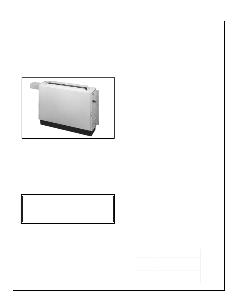
VCB SERIES (concealed applications)
Figure 5
WCB SERIES (recessed wall)
1) Mounting location must allow enough clearance to permit
the removal of all mechanical parts within the unit.
2) Frame the unit as required so the front panel of the wall unit
will be flush with the drywall surface when installed.
3) Frame around the perimeter of the unit as required for
securing the drywall. See figure 6 for required drywall
openings for each unit.
Remove or cover the secondary drain pan before solder-
ing the supply and return coil connections as hot solder
or the torch flame may damage the pan.
6) Solder the 5/8" coil connections in accordance with local
codes and regulations.
7) After coil connections have been made, check for leaks and
bleed the air from the system by venting each coil. (Figure
4)
8) After drywall has been installed recheck to make sure the
unit's front panel is flush with the exterior drywall surface.
If not, shimming the unit may be required to obtain a seal
between the unit and wall panel.
9) Install the wall panel to the front of the unit using the 1/4-20
x 1-1/2" long painted Phillips head screws (4 or 6 depend-
ing on the unit size). 1/4" cage nuts are located in the slotted
front panel of the unit for the panel screws to attach to.
Tighten the screws until the panel is secure with a good fit
against the wall.
10) Filter change / replacement can be performed by removing
the lower return air grille to access the filter within the unit.
****** WARNING ******
Proper framing and unit location is critical for unit
performance. Wall panel is required to seal against
the unit panel so there is no air leakage.
4) Mount the unit in its permanent location, making sure it is
level to insure proper drainage and operation, and secure
the unit in place. Two 1/2 inch holes have been provided
on each end of the unit for securing the unit to the studs. It
is recommended that all four mounting holes be used for
proper installation. (Figure 5)
5) Note the 1-1/2" x 4-1/2" indentation in the plastic drain pan
(Figure 3). This area is provided for the supply and return
runouts if they are brought up from below the pan. All piping
must be well insulated to prevent sweating. There is a 0.84"
OD condensate drain connection on the secondary drain
pan suitable to receive a standard 3/4" PVC coupling /
elbow.
-3-
Figure 6
MODEL
NUMBER
DRYWALL CUT-OUT DIMENSION
HEIGHT x WIDTH
3WCB
28" x 42"
4WCB
28" x 50"
6WCB
28" x 58"
8WCB
28" x 66"
10WCB
28" x 74"
12WCB
28’ x 82"