Dataprobe iBoot-G2 Quick Start User Manual
Quick start guide, What’s included, Available online at
Iboot-g2 quick start
© 2013 Dataprobe Inc.
V110120E
What’s Included
• iBoot-G2 Unit
• Power Input Cable for North America
• Power Outlet Cable for North America
• Network Cable
• Quick Start Guide
Available Online at
• Complete Product Manual
• Device Management Utility
• Latest iBoot-G2 Firmware
• Software Developer Tools
Connections
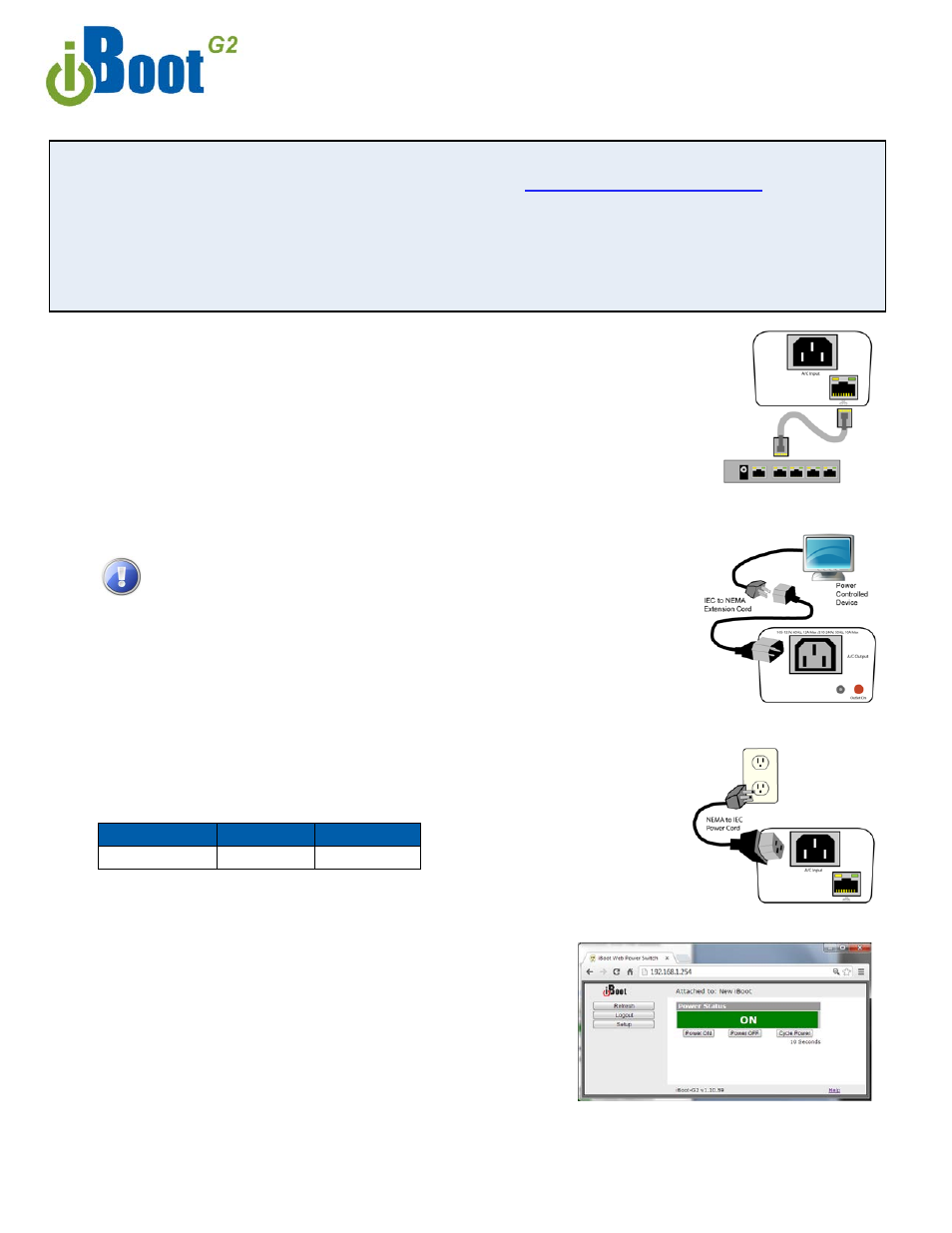
1.
Connect Network.
iBoot-G2
supports 10/100 Ethernet using the cable
supplied, or other suitable unshielded twisted pair (Cat 5) cabling. When power is
connected to the iBoot-G2, the green Activity LEDs on the network connector
indicate when the network connection is properly established.
2.
Connect Powered Device.
Connect the device to be powered ON and OFF
to the IEC receptacle marked A/C Outlet. An IEC-320 to North American (NEMA 5-
15) power cord is included for connecting the iBoot outlet to the device to be
controlled. If the device has a power switch, turn it on, to allow iBoot-G2 to control
the power.
Make sure that the combined load of all controlled devices
does not exceed 12 Amps for 105-125VAC or 10 Amps for 210-
240VAC.
3. Connect Power Mains
Connect the supplied power cord to the connector
labeled AC Input, and the other end to your AC source. If a power cord with a
different terminating plug is required, be sure it is properly rated and meets all the
required local electrical standards.
Web Browser Access
Factory Default IP Address: 192.168.1.254
Factory Default Security Credentials:
Role
Username
Password
Administrator
admin
admin
To access the iBoot from the default IP Address, requires the PC to be on the same
local network (IP Address 192.168.1.nnn). If it is not, change the
iBoot IP Address using one of the methods on the following page.
After pointing the browser to the IP Address of the iBoot, enter the
Administrator Username and Password to access the complete
setup features. Enter the User credentials to access only the power
control. Once the user is validated, the Control and Status is
displayed.
To control the power, click on the appropriate button. During power
cycling, the Power Status bar will indicate the temporary status, with
a blue background. Once the cycle is complete, the status bar will
revert to its original condition.
Quick Start Guide
Fig.1 Connect Network
Fig. 2 Connect Device
Fig. 3 Connect Power
Fig. 4 Status and Control Page
Document Outline
- What’s Included
- Available Online at dataprobe.com/support/iboot
- Connections
- Web Browser Access
- Quick Start Guide
- Changing the IP Address
- 2. Web Page Setup From the home page, click on Setup, then Network. Enter the new IP Address, Subnet Mask and Gateway, then click Save. Click the Reboot button (or press the reset button next to the power outlet LED) to restart the iBoot-G2 with th...
- Important Safety Instructions
- Mounting Options
- DIN Rail Mounting
- Installing the Wall Mounting Kit