Tdm wiring schematic, Tdm installation – Parr Instrument TDM User Manual
Page 5
TDM Installation
w w w . p a r r i n s t . c o m
5
Wiring installation in 4848 Reactor Controller (Continued)
8. Find the remaining black wire #2 from the kit
and attach one end to pin 1 on the 2084E meter.
Take care not to apply too much torque which could
cause the wire to break. (This may already be con-
nected for your convenience.) The other end attaches
to terminal block position #5.
9. Find the remaining white wire #1 from the kit
and attach one end to pin 2 on the 2084E meter.
Take care not to apply too much torque which could
cause the wire to break. (This may already be con-
nected for your convenience.) The other end attaches
to terminal block position #2.
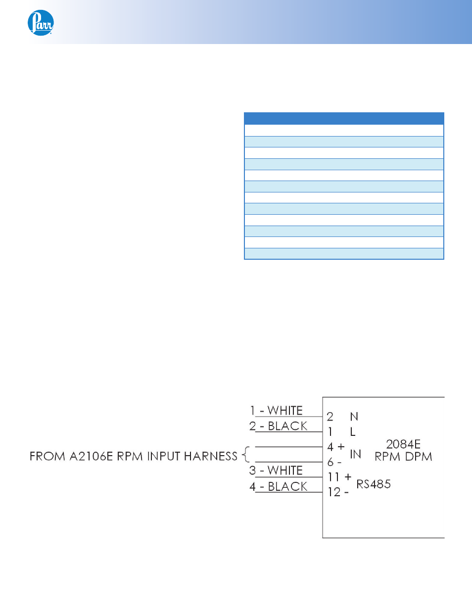
Pin Outs:
2084E
Color:
Attaches to:
Pin 1
Black
Terminal Block 5
Pin 2
White
Terminal Block 2
Pin 3
Pin 4
White
A1695E Excit Board
Pin 5
Pin 6
Black
A1695E Excit Board
Pin 7
Pin 8
Pin 9
Pin 10
Pin 11
White
Terminal Block 4
Pin 12
Black
Terminal Block 3
Final Steps:
Close the controller and replace the two screws on
the top plate. Plug the 4848 controller back in, and
turn it on. The RPM display should read zero when
the motor is not turning.
It is useful to check that the settings on the display
are set correctly. Check these against the defaults
listed in the back of these instructions.
TDM Wiring Schematic