American Energy Systems MagnuM 7500 User Manual
Page 36
36
o Control Board
molex connector
o Auger Motor
black wire to Vacuum Pressure switch (Com) grey wire to one lead
o Electrical Plug
double white wire to inside terminal (top, right side) Black/orange
wire to outside terminal (top, left side) green wire to bottom
terminal other end of green wire screwed to base of unit.
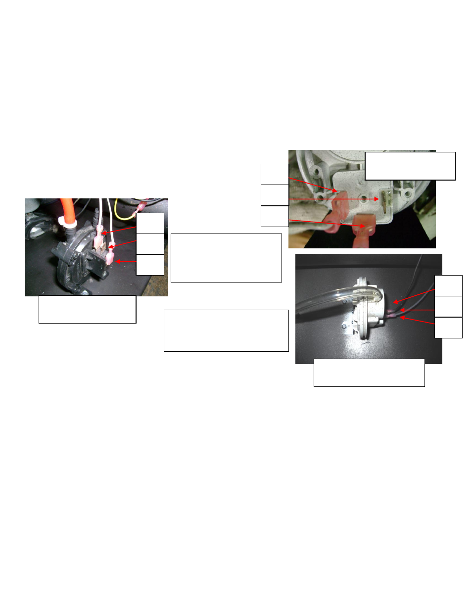
o Vacuum Pressure Switch
grey wire to left terminal black wire to middle terminal if Clark grey
wire to left terminal black wire to right terminal of World Magnetic
o Room Fan Sensor
double white wire to bottom terminal green wire to top terminal
o High Limit Sensor
blue wire to bottom terminal double grey to top terminal
o Room Air Fan
white wire to yellow wire black wire to double black wire
o Exhaust Fan
black wire to white wire red wire to black wire
Figure 17
N.O.
N.C.
COM
Attach one grey wire to ‘Com ’
and one grey wire to ‘NO’.
Attached hose to back
connection ‘L’.
RT080 World Magnetics
Vacuum Pressure Switch
Attach one grey wire to ‘Com 1’
and one grey wire to ‘NO 3’.
Attached hose to bottom connection
‘P2’.
N.O.
1
N.O.
2
N.O.
3
RT080 Clark Controls
Vacuum Pressure Switch
N.O.
1
N.O.
2
N.O.
3
looking in from side w/o
control panel