Model 500 – Bolens 115-500-000 User Manual
Page 15
Attention! The text in this document has been recognized automatically. To view the original document, you can use the "Original mode".
Model 500
PARTS LIST FOR MODEL 500 ROTARY MOWER
REF.
^0.
PART
NO.
COLOR
CODE
DESCRIPTION
NEW
PART
REF.
NO.
PART
NO.
COLOR
CODE
DESCRIPTION
NEW
PART
1
14320
Control Handle Ass’y-—R-H.
34
712-0123
Hex Nut 5/16-24 Thd.*
2
734-0244
Rear Wheel Ass’y.—Comp.
35
753-0348
Blade Adapter Kit ,
14.0
X
1.75
36
736-0217
L-Wash. 3/8" I.D.—H.D.
3
* *
Front Wheel Ass’y.—Comp.
37
736-0119
L-Wash. 5/16" I.D.*
8.0
X
1.75
38
14836
Retaining Strip
4
* *
Bearing
39
710-0776
Hex Wash. Hd. “AB”-Tap
5
* *
Axle Bolt—Front
Scr. 1/4 "
X
.62" Lg.
6
738-0481
Shoulder Bolt .50" Dia. x 2.62
40
731-0587
Rear Flap Ass’y.
7
742-0125
22" Blade
41
14924
Cable Bracket
8
746-0417
Throttle Wire—43" Lg.
42
728-0171
Pop Rivet .156 Dia. x .379
9
749-0373
Lower Handle (Chrome)
43
746-0478
Control Cable—Brake
749-0372
Lower Handle (Painted)
44
14919
—462
22" Deck Ass’y.
10
—
Engine
45
710-0654
Hex Wash. Hd. TT-Tap Scr.
11
11679
—462
Chute Deflector Ass’y.
3/8-16
X
1.00" Lg.
Comp.
46
710-0796
Truss Mach. “B”-Tap Scr.
12
11130
Adapter Plate
#12
X
1.50" Lg.
13
711-0555
Pivot Pin
47
726-0135
Cap Speed Nut 5/16" Rod
14
726-0106
Push Nut V4" Rod
48
731-0523
Control Panel Half
15
732-0253
Torsion Spring
49
731-0524
Control Disc Pin
16
710-0289
Hex Bolt 1/4-20
X
.50" Lg.*
50
731-0526
Clutch Panel Half
17
712-0287
Hex Nut 1/4-20 Thd.*
51
731-0528
Throttle Control Lever
18
736-0329
L-Wash. 1/4" I.D.*
52
749-0536
Upper Handle (Chrome)
19
12935
Handle Mount Brkt.—L.H.
749-0538
Upper Handle (Painted)
20
12936
Handle Mount Brkt.—R.H.
53
714-0104
Intern. Cot. Pin 5/16" Dia.
21
710-0603
Hex Wash. Hd. “B” Tap Scr.
54
726-0192
Cable Tie
5/16-18
X
.50" Lg.
55
710-0671
Curved Carriage Bolt 5/16-18
22
14068
Extension Brkt.—R.H.
X
1.38" Lg.
23
14069
Extension Brkt.—LH.
56
710-0842
Rope Guide Bolt
710-0209
Hex Sems Bolt 3/8-16 x .62"
57
712-0267
Hex Nut 5/16-18 Thd.*
Lg.*
58
736-0119
L-Wash. 5/16" I.D.*
25
710-0258
Hex Bolt 1/4-20
X
.62" Lg.*
59
710-0429
Hex B-Tap Scr. #10 x .38" Lq.
26
710-0603
Hex Wash. Hd. “B” Tap Scr.
60
751-0369
Casing Clamp
5/16-18
X
.50" Lg.
61
12894
Casing Clamp
27
712-0287
Hex Nut 1/4-20 Thd.*
62
777-3455
Instruction Label—Handle
28
712-0297
Oval Nut 3/8-16 Thd.
63
777-5168
Control Label—Throttle
N
29
736-0105
Bell-Wash. .400" I.D. x .88"
64
753-0360
Control Housing Comp.
O.D.
(Incl. Ref. Nos. 46, 48, 49,
30
736-0329
L-Wash. 1/4" I.D.*
50, 51 & 63)
31
749-0400
Stabilizing Strut
65
748-0147
Flange Bearing
32
710-0888
Hex Bolt 5/16-24 x 1.00" Lg.
66
710-0227
Hex Wash. Hd. AB-Tap Scr.
(Grade 5)
#8
X
.38" Lg.
33
710-0331
Hex Bolt 3/8-24 x 2.25" Lg.
67
731-0564
Plastic Plug
(Grade 5)
—
8500-000-5
Hardware Pack
For faster service obtain standard nuts, boits, and washers locally. If these items cannot be obtained locally, order by part number
and size as shown on parts list.
(462—Red Flake) When ordering parts if color or finish is important, use the appropriate color code shown at left. (e.g.
Finish—14483 (462).)
-Red Flake
NOTE
This instruction manual covers various models
and all specifications shown do not necessari
ly apply to your model. Specifications subject
to change without notice or obligation.
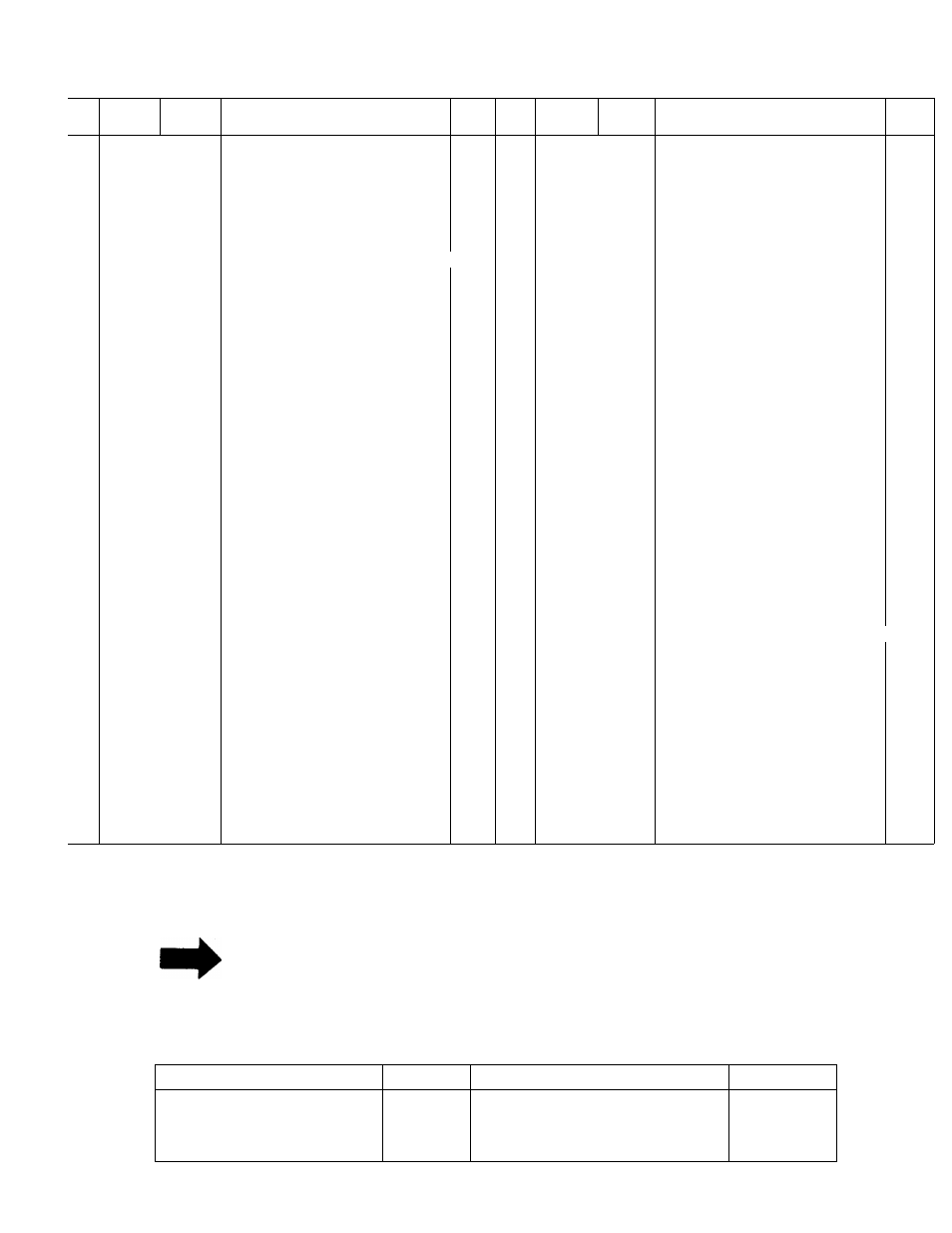
**FRONT WHEEL CHART
NOTE: The engine is not under warranty by
the
mower
manufacturer..
.If
repairs
or
service is needed on the engine, please
contact your nearest author-
a
--------------—-—■
ized engine service outlet.
Find It Fast
Check the “Yellow Pages” of
In The
your telephone book under
Yellow Pages
“Engines—Gasoline.”
Type of Wheel
Part No.
Bearing Part No.
Axle Bolt
Plastic
Steel
w/Fortiflex
Bearings
Steel w/Ball Bearings
734-0841
734-0661
734-0645
1/2" I. D.—741-0262 (2 per wheel)
3/8" I.D.—741-0267, Vz" I.D.—
741-0484, Spacer—750-0434
738-0213
738-0213
710-0427
15