MUTEC MC-3+ Smart Clock User Manual
Page 20
\\\\\\\\\\\\
AP P E N D I X
AP P E N D I X
AP P E N D I X
> > > > > > > > > > > > > > > > > > > > > > > > > > > > > > > > > > > > > > > > > > > > > > > > > > > > > > > > > > > > > > > > > > > >
> > > > > > > > > > > > > > > > > > > > > > > > > > > > > > > > > > > > > > > > > > > > > > > > > > > > > > > > > > > > > > > > > > > >
88
Manual SDs-01 E 3.2.2003 18:26 Uhr Seite 14
20
Technical Data
WORD CLOCK + 10.0M INPUT
Interface
1 x BNC, 200 mV-7 V, unbalanced, input impedance 75 Ω (can be switched off, see above)
Lock
Range
25.0kHz to 200.0 kHz, 10.0MHz, 11.2896MHz + 12.288MHz (so-called Super Clocks)
AES3 AUDIO INPUT
Interface
1 x XLR female, transformer balanced, input impedance 110 Ω, 200 mV – 7.0 V
Format, Resolution
AES3 – 1992/2003, AES11 – 1997/2003, IEC 60958, 16 – 24 bits
Lock Range
25.0kHz to 200.0kHz
S/P-DIF OPTICAL AUDIO INPUT (OP)
Interface
1 x Toslink
TM
, EIAJ RC-5720
Format, Resolution
IEC 60958, 16 – 24 bits
Supported Sampling Rates
25.0kHz to 200.0kHz
S/P-DIF COAXIAL AUDIO INPUT (CO)
Interface
1 x Coaxial (RCA female), unbalanced, 0.5 –1.0Vpp @ 75 Ω, output impedance 75 Ω
Format, Resolution
IEC 60958, 16 – 24 bits
Supported Sampling Rates
25.0kHz to 200.0kHz
WORD CLOCK OUTPUTS (WCLK)
Interface
1 x BNC, 3,0 V @ 22 Ω, unbalanced, buffered
Transmitted Clock Rates
25.0kHz to 768.0kHz, 11.2896MHz + 12.288MHz (so-called Super Clocks)
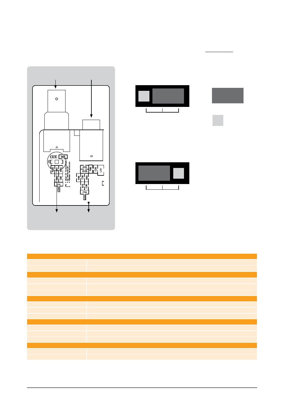
Switching-off the Termination of the Word Clock Input
CAUTION! Disconnect the unit from the mains before opening!
Remount the aluminium cover thoroughly before you attempt to operate
the unit!
When the MC-3+ Smart Clock is shipped, the BNC-based Word Clock input
connector is terminated internally with 75 Ω. Therefore, one jumper is put
on two pins - Position 2 - of the 3-pin socket JP1.
When moving the jumper from position 2 to position 1, the input termi-
nation will be switched-off. Therefore, the MC-3+ must be connected in a
chain, in which a device with terminated input follows. Otherwise you need
to use a BNC-T piece in combination with a 75 Ω BNC resistor for terminat-
ing the MC-3+’s input.
JP2
Jumper:
1
2
Free Pin:
Jumper Position 2
= Termination
For additional information regarding this issue, please refer to page 11
under »Wiring the Word Clock Interfaces«.
JP2
1
2
Jumper Position 1
= no Terminaltion
Word Clock Termination
Word Clock
Input
Termination
3-pin socket
JP1
S/P-DIF
Inputs
MC-3+
Mainboard
PCB