MUTEC MC-3+ Smart Clock User Manual
Page 17
\\\\\\\\\\\\\\\\\\
A N H A N G
A N H A N G
A N H A N G
> > > > > > > > > > > > > > > > > > > > > > > > > > > > > > > > > > > > > > > > > > > > > > > > > > > > > > > > > > > > > > > > > > > >
> > > > > > > > > > > > > > > > > > > > > > > > > > > > > > > > > > > > > > > > > > > > > > > > > > > > > > > > > > > > > > > > > > > >
88
Manual SDs-01 D 3.2.2003 17:45 Uhr Seite 16
Selecting Clock Multipliers
Pressing the »MENU« key changes from the »REFERENCE» to the »CLOCK
MULTIPLIERS
« menu. Here you can select for every pair of Word Clock and the
digital audio outputs individual clock rate multiplication factors of x1, x2,
x4 and x256 by pressing the »SELECT« key repeatedly. The multiplication
factors refer always to the basis clock rate of the incoming reference signal
or the clock rate selected of the internal ultra-low-jitter clock generator
(»INTERNAL + 10.0M«). Thus, dependently of the incoming or selected basis
clock rate, the MC-3+ covers a range auf audio related clock rates from
32.0kHz up to 768.0kHz plus the two so-called Super Clocks (see below).
The setting »x 256«, or so-called Super Clock, is only available for the three
pairs of Word Clock outputs. It transmits either a clock rate of 11,289.6MHz
(44.1kHz x 256) or 12,288.0MHz (48.0kHz x 256). The system analysis in any
way the basis clock rate of the incoming or the generated reference clock
signal, 44.1kHz or 48.0kHz, and outputs the corresponding Word Clock
x 256 for use with older digidesign ProTools
TM
systems.
The multiplication of the digital audio outputs S/P-DIF (»4«) and AES3/11
(»5«) is limited to a maximum clock rate of 192.0kHz, regardless of the clock
rate of the reference signal.
Multiplying Digital Audio
Signals
When having a digital audio input
selected as reference and setting the mul-
tiplication factor to higher than »x 1«, the
MC-3+ outputs a blank frame signal only at
the audio outputs. A sampling rate conver-
sion of the incoming digital audio signal is
not carried out.
!
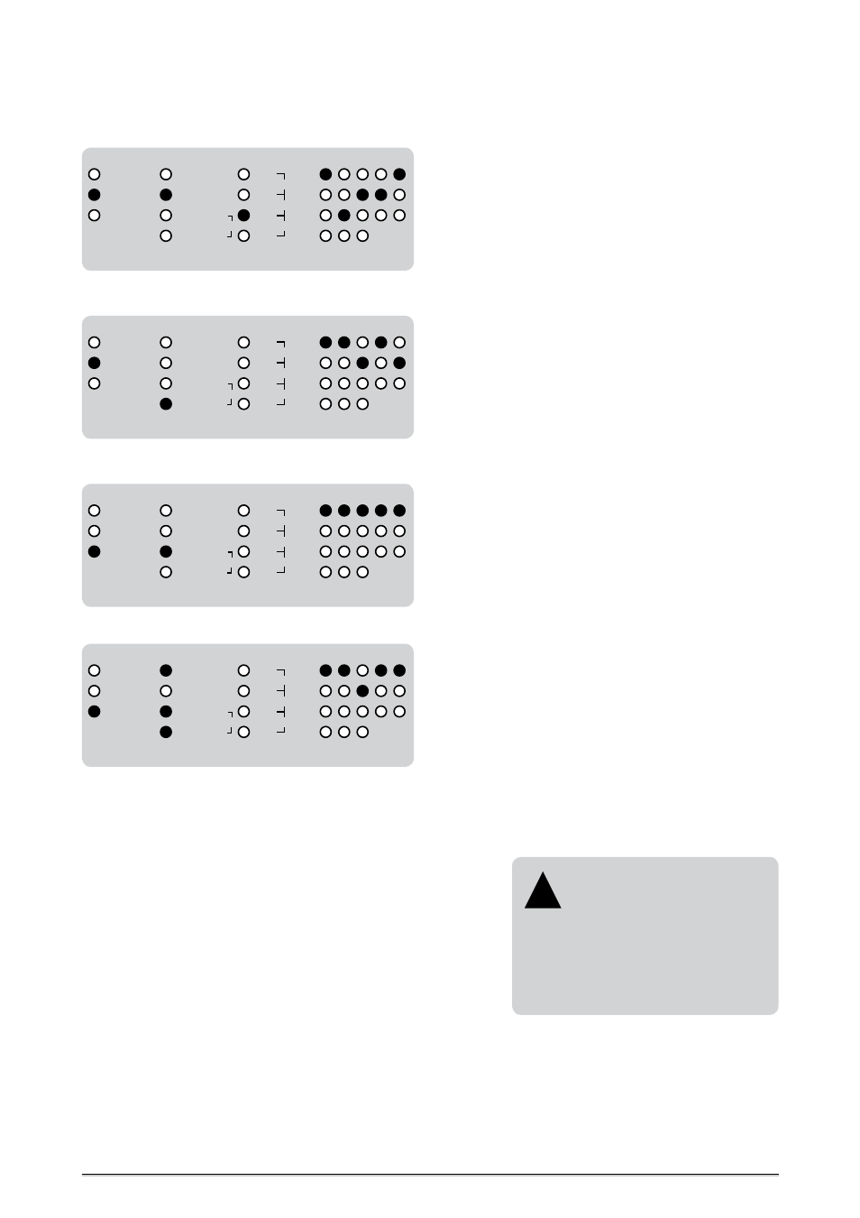
An AES3 signal is asynchronous re-clocked with an additional Word Clock signal. All outputs provide
their signals with same clock rate like this one of the incoming AES3 digital audio signal, except the
Word Clock output 3 is set to output the double clock rate of the reference signal.
A 10.0MHz clock signal is applied as reference and the basis clock of all outputs is set to 48.0kHz.
The outputs provide different multiples of the basis clock rate due to the adjustments of the clock
multipliers. All four red LEDs in the »CLOCK
IN
« area light to show that a 10.0MHz reference comes in.
MODE
RE-CLOCK
EXTERNAL
INTERNAL
x 256
x 4
x 2
x 1
CLOCK
MULTIPLIERS
1
5
4
3
2
REFERENCE
S/P-DIF op
S/P-DIF co
88.2
48.0
44.1
32.0
192.0
96.0
176.4
10.0M
WCLK
INTERNAL + 10.0M
AES3/11
17
Further Setting Examples
MODE
RE-CLOCK
EXTERNAL
INTERNAL
x 256
x 4
x 2
x 1
CLOCK
MULTIPLIERS
1
5
4
3
2
REFERENCE
S/P-DIF op
S/P-DIF co
88.2
48.0
44.1
32.0
192.0
96.0
176.4
10.0M
WCLK
INTERNAL + 10.0M
AES3/11
An optical S/P-DIF digitalaudio signal is synchronous re-clocked. All outputs provide their signals on
the same clock rate like this one of the incoming optical S/P-DIF digital audio signal.
MODE
RE-CLOCK
EXTERNAL
INTERNAL
x 256
x 4
x 2
x 1
CLOCK
MULTIPLIERS
1
5
4
3
2
REFERENCE
S/P-DIF op
S/P-DIF co
88.2
48.0
44.1
32.0
192.0
96.0
176.4
10.0M
WCLK
INTERNAL + 10.0M
AES3/11
A coaxial S/P-DIF digital audio signal is applied as reference. All outputs provide their clock rates
aligned to the selected multiplication factors. The S/P-DIF (»4«) and AES3/11 (»5«) outputs supply
blank frame signals.
MODE
RE-CLOCK
EXTERNAL
INTERNAL
x 256
x 4
x 2
x 1
CLOCK
MULTIPLIERS
1
5
4
3
2
REFERENCE
S/P-DIF op
S/P-DIF co
88.2
48.0
44.1
32.0
192.0
96.0
176.4
10.0M
WCLK
INTERNAL + 10.0M
AES3/11