Vi. set-up – Kistler-Morse KM Load Stand II User Manual
Page 21
17
www.kistlermorse.com
97-1100-01 Rev. H
vI. SET-uP
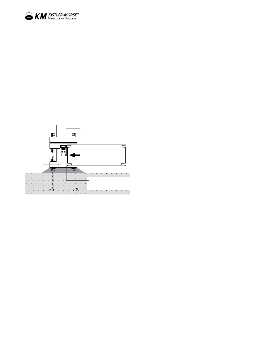
inStaLLinG a Sun ShieLD
The sun shield reduces sun-induced stresses in the Load Stand sensors and provides additional protection for
the sensors.
1. With the junction box cover off, slightly loosen the screws attaching the junction box to the Load Stand.
2. Slightly loosen the horizontal screw(s) on the bottom flange of the Load Stand.
3. Wrap the sun shield around the Load Stand, slipping the cutout slots behind the loosened screws.
4. Tighten the junction box screws and the horizontal screw(s) on the bottom flange.
5. Replace the junction box cover.
Screw not
on all models
Slide sun shield behind junction
box and loosened screws.
Wrap sun shield around
Load Stand. Slide shield behind
junction box and loosened screws
on other end.
Loosen Junction Box screws;
Re-tighten after Sun Shield
is installed.
Loosen Bottom Flange Screw(s);
Re-tighten after Sun Shield
is installed.
caLiBration
There are two calibration methods:
• Live Load calibration — set low span and high span while moving material into or out of the vessel. This is
the preferred method.
• Manual calibration — set scale factor counts, scale factor weight, and zero calibration value without
moving material.
Live Load calibration requires you to move a known quantity of material into or out of the vessel while performing
the procedure. The quantity of material moved must be at least 25% of the vessel’s total capacity to provide best
accuracy. Live Load calibration is also based on the material weight currently in the vessel. Manual calibration
allows you to start using the system as soon as Load Stands and signal processor are installed and wired, even
if you cannot move any (or enough) material now. Manual calibration values are based on system parameters,
including sensor sensitivity, rated load, and signal processor A/D converter sensitivity. These values are known,
can be calculated, or can be obtained from the signal processor. Manual calibration is also based on the material
weight currently in the vessel.
Note that manual calibration does not take into account the actual response to changes in weight. Theoretically,
a change in weight results in a proportional change in digital counts. However, the structure’s actual response
to weight and interaction with piping catwalks, roof, discharge chutes, etc. prevents the system from achieving
theoretical values. Manual calibration is a good start, but to obtain the highest accuracy, perform a Live Load