Receiver operation, Warning: to clear a latched fault or alarm, press, Activated led – Inovonics FA404 User Manual
Page 5: Reset, Fa404r, 3-way configuration panel, Resistor provided with hardwire panel
© 1998 Inovonics Wireless Corporation LIT-FA404-INSTALL
5
02327C.DOC 8-Oct-01
Receiver Operation:
Output activation: The FA404 has N/O open collector Alarm and Fault outputs. Output is open relative to ground.
On activation, output pulls to common ground. The FA404R has Form C Alarm and Fault relay outputs. Output
activation is indicated by illumination of the
ACTIVATED LED
. Note: if a receiver is being connected to a normally
closed zone, the FA404R must be used.
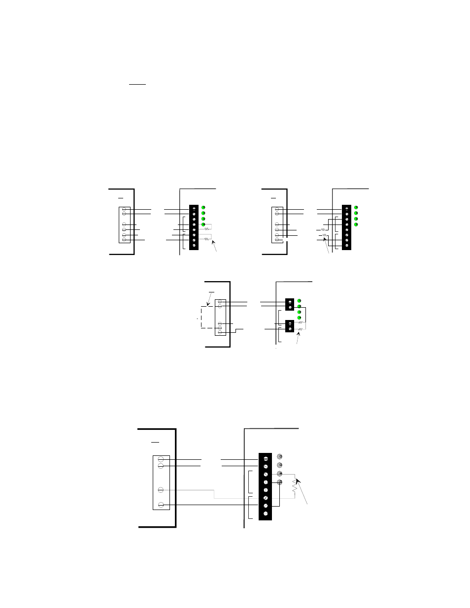
Connection to hardwire panels: When an FA404 or FA404R receiver is used with a hardwire security panel, the
panel will typically supply power and ground to the receiver. When the ground supplied to the receiver is common
to the return loops of the hardwire panel, use one wire to connect each of the FA404 receiver outputs to the zone
input of the panel. Supervision resistors in N/O loops must be placed in parallel. Supervision resistance in N/C
loops must be in series. The examples below show typical connections of both the FA404 and the FA404R.
13.6V
GND
N/C
N/O
COM
13.6V
GND
N/C
COM
N/O
N/C
N/O
F
A
UL
T
A
L
A
RM
13.6VDC
GROUND
FAULT SUPERVISION ZONE
NOTE: GROUND AND
RETURNS ARE COMMON.
FA404
PANEL
RETURN
ALARM ZONE
EOL resistors, if required
13.6V
GND
N/C
N/O
COM
13.6V
GND
N/C
COM
N/O
N/C
N/O
FA
U
L
T
AL
A
R
M
13.6VDC
GROUND
ALARM ZONE
FAULT ZONE RETURN
ALARM ZONE RETURN
FAULT SUPERVISION ZONE
FA404R, N/O configuration
PANEL
NOTE: GROUND AND
RETURNS ARE NOT
COMMON.
EOL resistors, if required
for N/O configuration
13.6V
GND
N/C
N/O
COM
13.6V
GND
N/C
COM
N/O
N/C
N/O
F
A
UL
T
A
L
A
RM
13.6VDC
GROUND
ALARM ZONE RETURN
FA404R, N/C configuration
PANEL
NOTE: GROUND AND
RETURNS ARE NOT
COMMON.
FAULT ZONE RETURN
FAULT ZONE
ALARM ZONE
EOL resistors, if required
for N/C configuration
WARNING: To clear a latched fault or alarm, press
RESET
. Make sure that the receiver is not in program mode
or the transmitter will be deleted. Test all transmitters prior to leaving the site.
If the panel has N/O zones and can recognize 3 zone conditions (open=fault, short=alarm and EOL
resistance=normal), both the alarm and the fault outputs can be attached to the same zone as shown below.
13.6V
GND
N/C
N/O
COM
13.6V
GND
N/C
COM
N/O
N/C
N/O
FA
U
L
T
AL
A
R
M
13.6VDC
GROUND
ZONE INPUT
FA404R, 3-WAY CONFIGURATION
PANEL
NOTE: GROUND AND
RETURNS ARE NOT
COMMON.
COMMON
Resistor provided with
hardwire panel