Technical specifications, Installation – Inovonics FA404 User Manual
Page 3
© 1998 Inovonics Wireless Corporation LIT-FA404-INSTALL
3
02327C.DOC 8-Oct-01
Technical Specifications:
Dimensions (housing):
6.38" x 3.60" x 1.10"
Weight:
6.9
oz.
Environmental:
Operating
temperature:
32
°
-120
°
F (0
°
-50
°
C)
Relative Humidity:
95% (non-condensing)
Electrical:
Power Requirement:
11-14 VDC
Power Consumption:
130mA (max, relays activated)
Typical:
40mA
(quiescent)
FA404R output relay
Form C, 1A @ 28VDC, 0.5A @ 30VAC (resistive)
Receiver:
Type:
frequency-hopping spread spectrum
Operating frequency:
902-928 MHz
The
VALID DECODE LED
indicates transmissions from transmitters programmed to the receiver.
The receiver programs transmitters with the following fixed parameters:
•
No EOL resistor.
•
No Internal Contact. (The FA404 and FA404R will not support the FA200W or FA210W widegap
internal magnet contact.)
•
60-second supervisory check-in. (The transmitter sends a supervisory signal every 60 seconds. Some
transmitters check in at 150-second intervals.) The receiver, with a fixed 4-hour supervisory window,
will declare a programmed point inactive if no transmission is received during every 4 hour window.
•
The Fault Output is Latching for low battery or tamper faults. It is Follower for Inactive faults.
•
The Alarm Output is user-selectable to be follower, momentary, latching or toggle.
Note: FA transmitters have non-volatile memory. It is not necessary to reprogram transmitters after losing
power or changing batteries. Press the transmitter reset button to restore programming.
Installation:
Power: Supply power and ground to terminals marked 13.6V and GND on the terminal block.
Mounting: Use supplied hardware to attach FA404 or FA404R housing to wall or surface. To route wiring
out the back of the unit, use a small side cutter or utility knife to remove the knockout in the housing base.
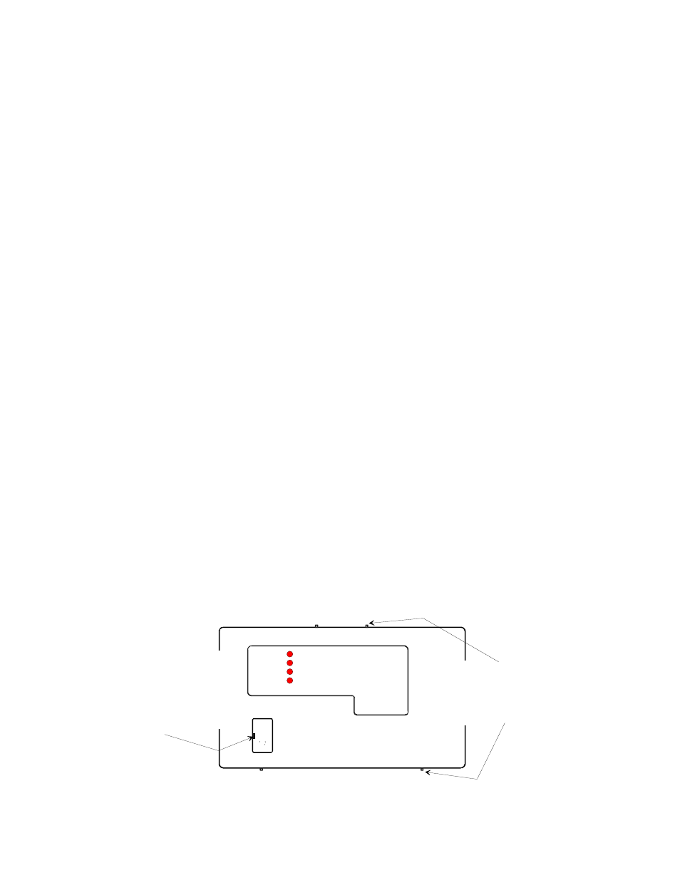
Opening the housing:
ACTIVATED
TAMPERED
LOW BATTERY
INACTIVE
Frequency Agile
Receiver
by Inovonics Corporation
Insert a small flat screwdriver
behind pry point indicator nubs
on top or bottom of the housing
cover (4 places). Gently pry or
twist the housing cover apart.
Reset Button Access Cover:
Insert small screwdriver
in slot on left side. Hold cover
lightly while prying. Install by
inserting top latch and
snapping in at bottom.