Electrical installation and interconnection, Electrical installation and interconnection –18 – Vinten Radamec SP-2000 Pedestal User Manual
Page 58
SP-2000/X-Y
Installation
3-18
User Manual
Electrical Installation And Interconnection
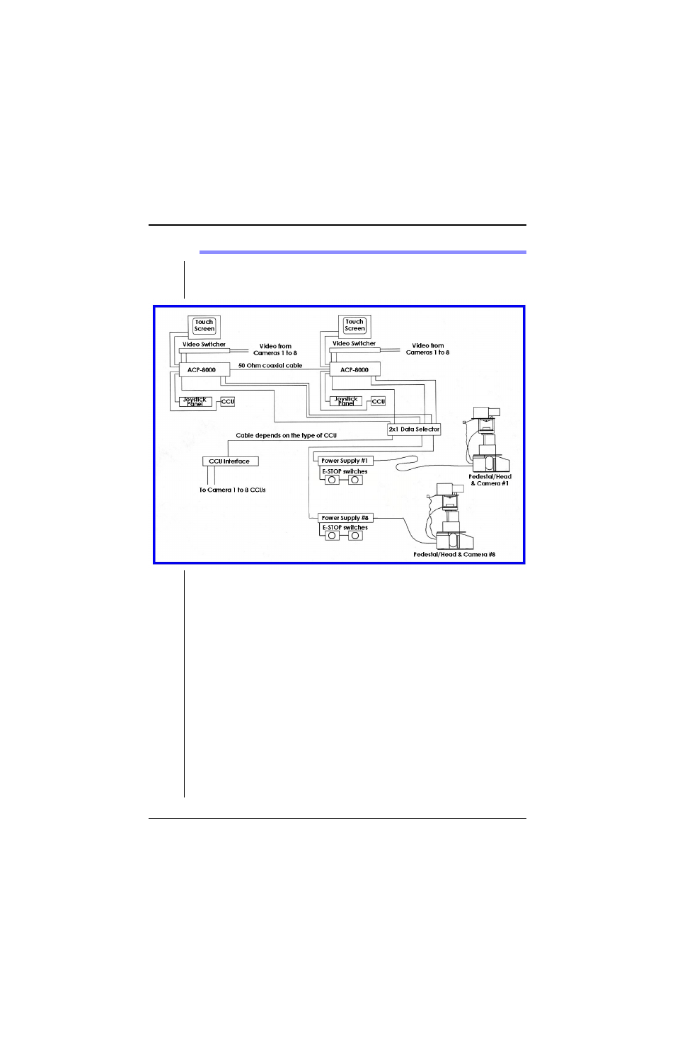
A typical AutoCam system configuration is shown below..
1.
Refer to the User Manuals for the controller, the pan/tilt head and other
equipment for relevant installation instructions.
2.
The rackmount power supplies are installed up to 260 ft. (80 m) from their
respective pedestals - refer to the User Manual for the power supply for
additional information.
See also other documents in the category Vinten Radamec Equipment:
- 435H Pan & Tilt Head (10 pages)
- AutoCam Multicontroller II (62 pages)
- Ci Box ICE Interface (20 pages)
- e-Series Interface (7 pages)
- FHR-35 (36 pages)
- Free-d (46 pages)
- Fusion APS (28 pages)
- Fusion Camera Control Unit (CCU) (20 pages)
- Fusion CP4 (36 pages)
- Fusion FBH-175 (24 pages)
- Fusion FCS-16 (40 pages)
- Fusion FH-100 (38 pages)
- Fusion FH-200 (24 pages)
- Fusion FHR-100VR (44 pages)
- Fusion FHR-120 (40 pages)
- Fusion FHR-145 (24 pages)
- Fusion FP-145 (30 pages)
- Fusion FPH-188 (38 pages)
- Fusion FPR-210 (36 pages)
- Fusion Virtual Reality box (FVR) (20 pages)
- Head Processing Module (HPM) (20 pages)
- HS-102PE Pan & Tilt Head (30 pages)
- HS-105PE Pan & Tilt Head (28 pages)
- HS-2010MED Pan & Tilt Head (70 pages)
- ICE Tool (24 pages)
- Legislative Control System (34 pages)
- Native Lens Drive (NLD) (19 pages)
- Quattro SE HPM (23 pages)
- Quattro SE PDA (36 pages)
- Quattro SE Pedestal (30 pages)
- SE-500 Elevation Unit (33 pages)
- Control (VRC) (100 pages)
- HDVRC (70 pages)
- Virtual Reality interface (VRi) (24 pages)
- Vision 250E (18 pages)