KMC Controls REE-5525 User Manual
Installation guide, Connections and wiring, Sequence
REE-5525 Relay Module
1
Installation Guide
Installation Guide
Proportional to Tri-State Control, Relay Module
REE-5525
Mounting 1
Sequence 1
Connections and Wiring 1
Specifications 2
Maintenance 2
Troubleshooting 2
Important Notices 2
Mounting
The module may be mounted directly to a control
box surface or in a 2 x 4" electrical handy box. Add a
blank cover to conceal the module if desired.
Connect as shown. Supply the relay with 24 VAC
(+20%/–15%, Class 2 only). (Use wire size of 14 to 22
AWG, stranded.)
NOTE: The 24 VAC sources can be the same or
separate, with no regard to phasing.
NOTE: Triac outputs are for 24 VAC loads only.
Outputs are optically isolated from the
control 24 VAC power.
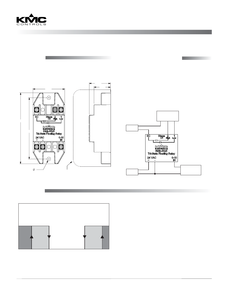
Connections and Wiring
3.25
3.77
1.69
0.19
MOUNTING HOLES
0.88
1.13
FITS STANDARD 2" DEEP x 2-1/8"
UTILITY BOX & BLANK COVER PLATE
All dimensions are in inches
TYPICAL
APPLICATION
24 VAC
24 VAC
+
0–10 VDC
SIGNAL
–
ACTUATOR
COM CW CCW
The stage sequence operates in this manner:
• Stage 1 turns on at or below 1.5 VDC* and off at
or above 3.5 VDC. (It is on at 0 VDC.)
• Stage 2 turns on at or above 9.5 VDC* and turns
off at or below 7.5 VDC. (It is on at 10 VDC.)
• Both outputs are off between 3.5 and 7.5 VDC.
Sequence
STAGE 2 ON
STAGE 1 ON
BOTH
STAGES
OFF
INPUT SIGNAL VDC
0 1.5 3.5 5 7.5 9.5 10
SEQUENCE
*NOTE: In the dark grey regions of the chart, the
stage is definitely on for the given voltage.
In the light grey regions, however, on or
off depends on the previous state. For
example, at 2 VDC, Stage 1 will be on if the
previous voltage was 0 VDC (Stage 1 on)
but off if the previous voltage was 5 VDC
(Stage 1 off).