Series md - b15 / md - b40 coupling, Caution – Viking Pump TSM680: 895, 893 and 897 Mag Drive User Manual
Page 8
SECTION TSM
680
ISSUE
G
PAGE 8 OF 17
Series MD - b15 / MD - b40 Coupling
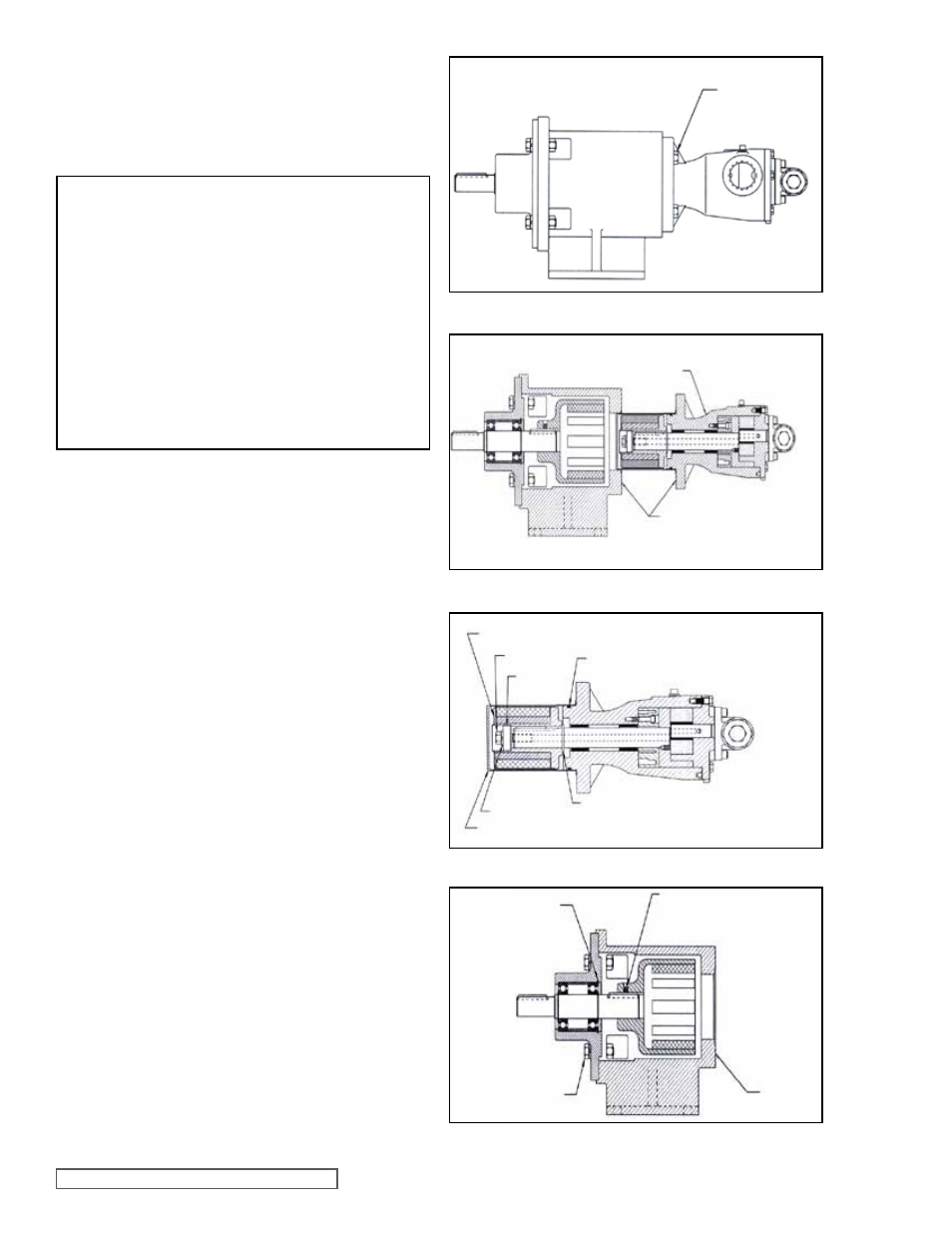
1. Remove the piping to the ports and remove the
capscrews securing the pump to the bracket
(See
Figure 15). Support the pump with an overhead hoist if
possible.
CAUTION !
Do not place your fingers between the pump
mounting flange and the face of the bracket.
Using extreme caution, pull the inner magnet
away from the outer magnet (see figure 16). If
you do not completely pull the pump out it will
snap back and could pinch a finger or hand.
Once the inner magnet is removed from the
bracket be careful setting it down as it will at-
tract any iron or steel object.
2. The canister will probably be full of liquid, therefore use
care while removing from the pump and pull it straight
off.
3. Insert a brass bar through a port between two rotor teeth
and loosen the capscrew holding the inner magnet to
the shaft
(See Figure 17). Slide the washer, lock washer
and inner magnet off the shaft. Do not forget this is a
very strong magnet. If pump disassembly is required,
remove second external retaining ring.
4. Do not remove the o-ring unless it is bad, especially
if PTFE (Derivative) Encapsulated. If a new o-ring is
required, follow instructions in the
ASSEMbLY section
on
page 11.
5. You should be able to visually inspect the outer magnets
from the end of the bracket. If removal is necessary,
start by removing the (4) capscrews
(See Figure 18)
and separating the bracket from the motor or bearing
carrier. Loosen the setscrews on the motor or bearing
carrier shaft and pull the outer magnet assembly off. If
the unit features a bearing carrier, the bearings should
not require maintenance since they are sealed. If
necessary, disassemble by removing the single internal
retaining ring then press the shaft and bearings out of
the housing. Remove the external retaining rings from
the shaft to remove the bearings.
PUMP – BRACKET
0.5” CAPSCREWS
(4) REQUIRED
DO NOT PLACE
FINGERS HERE
PLACE HANDS BACK HERE
INNER MAGNET ASSEMBLY
STATIC O-RING
CAPSCREW
WASHER
RETAINING RING
LOCK
WASHER
CANISTER
COUPLING
BRACKET
CAPSCREWS
(4) REQUIRED
INTERNAL
RETAINING
RING
SETSCREWS
(2) REQUIRED
FIGURE 15
FIGURE 16
FIGURE 17
FIGURE 18