Straight pattern, Materials of construction, Pressure – temperature dimensions—weights – Watts CSM-91 User Manual
Page 2: Installations, Flange adapter details, Elastomers, Ductile iron flange adapters for ansi 150# flanges, Grooved end with 375psi rated pipe coupling
Straight Pattern (Stan dard)
Straight Pattern
Size (DN)
DiMeNSioNS
FlaNge Dia. 125#
SpaCer
Weight
A
C
D
F
in.
mm
in.
mm
in.
mm
in.
mm
in.
mm
in.
mm
in.
mm
lbs
kgs
2
1
⁄
2
65
12
305
9
5
⁄
8
245
2
3
⁄
4
70
2
9
⁄
16
65
7
178
1
25
19
9
3
80
12
305
10
1
⁄
2
267
2
7
⁄
16
62
3
76
7
1
⁄
2
191
1
25
24
11
4
100
14
356
10
9
⁄
16
268
3
76
3
7
⁄
16
87
9
1
⁄
4
235
1
1
⁄
4
32
42
19
5
125
17
1
⁄
2
445
13
1
⁄
16
332
3
5
⁄
8
92
4
15
⁄
16
125
10
254
1
1
⁄
4
32
81
37
6
150
20
11
⁄
16
525
13
3
⁄
4
349
4
7
⁄
16
113
5
7
⁄
8
149
11
279
2
51
120
54
8
200
28
3
⁄
16
716
24
5
⁄
8
625
5
11
⁄
16
144
7
7
⁄
8
200
13
1
⁄
2
343
2
1
⁄
4
57
310
141
10
250
30
762
26
1
⁄
2
673
6
9
⁄
16
167
9
15
⁄
32
241
16
406
2
1
⁄
4
57
460
209
Materials of Construction
Body
Ductile Iron ASTM A536 GR65-45-12
Disc
Bronze ASTM B584 C-84400
Seat
2
1
⁄
2
" – 6" Engineered Resin
8" – 10" EPDM
Stem
Brass ASTM B-16 2
1
⁄
2
" – 6" (65 – 150mm)
Stainless Steel 8" – 10" (200 – 250mm)
O-ring
Buna-N
Memory Lock
Brass ASTM B-16
Meter Ports
NPT Brass body with Schrader Valve
Drain Tappings (2)
1
⁄
4
" Brass plug
Optional Equipment
Flange Adapters
Ductile iron
Flange Gaskets
EPDM
Insulation Fiberglass
Note: Series CSM-91 valves are shipped with grooved ends stan dard. For com-
pan ion flang es, please specify size and class rat ing when or der ing. In su la tion
blocks are also or dered sep a rate ly from valve. Please spec i fy size when or der ing.
Pressure – Temperature
Dimensions—Weights
Spac er
t
Flange
Dia.
Installations
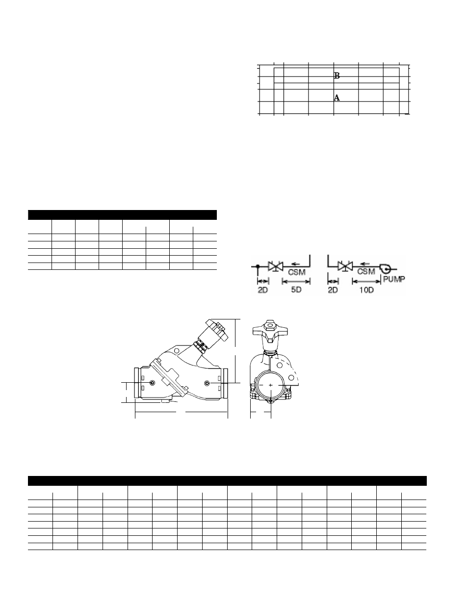
Generally locate the valve five pipe diameters downstream from a
fitting; with two diameters downstream from the balancing valve
free from fittings. If a balancing valve is located downstream from
a circulation pump, allow a distance of ten (10) diameters between
the pump and balancing valves (as illustrated below).
Flange Adapter Details
ValVe Size
pipe o.D.
125pSi
Bolt
Bolt Circle Diam.
in.
mm
in.
mm
No.
Size
in.
mm
2
1
⁄
2
64
2
7
⁄
8
73
4
5
⁄
8
x 3
5
1
⁄
2
140
3
76
3
1
⁄
2
89
4
5
⁄
8
x 3
6
152
4
102
4
1
⁄
2
114
8
5
⁄
8
x 3
7
1
⁄
2
191
5
127
5
9
⁄
16
140
8
3
⁄
4
x 3
1
⁄
2
8
1
⁄
2
216
6
152
6
5
⁄
8
168
8
3
⁄
4
x 3
1
⁄
2
9
1
⁄
2
214
temperature ˚C
temperature ˚F
Note:
For temperatures between 230˚F and 300˚F
(110˚C and 149˚C), specify Viton
®
Elastomers
pressure psi
pressure k
pa
-46˚ -29˚ -18˚
10˚
38˚
66˚
93˚
110˚
-50˚ -20˚ 0˚
50˚
100˚
150˚
200˚
230˚
400
375
300
250
200
100
0
2760
2585
2070
1724
1380
690
250
legend
A –
Ductile iron flange adapters for ANSI 150# flanges
B –
Grooved end with 375psi rated pipe coupling
2
D
A
C
F