Watts CSM-91 User Manual
Series csm-91, Flow measurement/balancing valves, For balancing and flow measurement applications
For Balancing and Flow Measurement Applications
ES-CSM-91
Series CSM-91
Flow Measurement/Balancing
Valves
Sizes: 2
1
⁄
2
" – 10" (65 – 250mm)
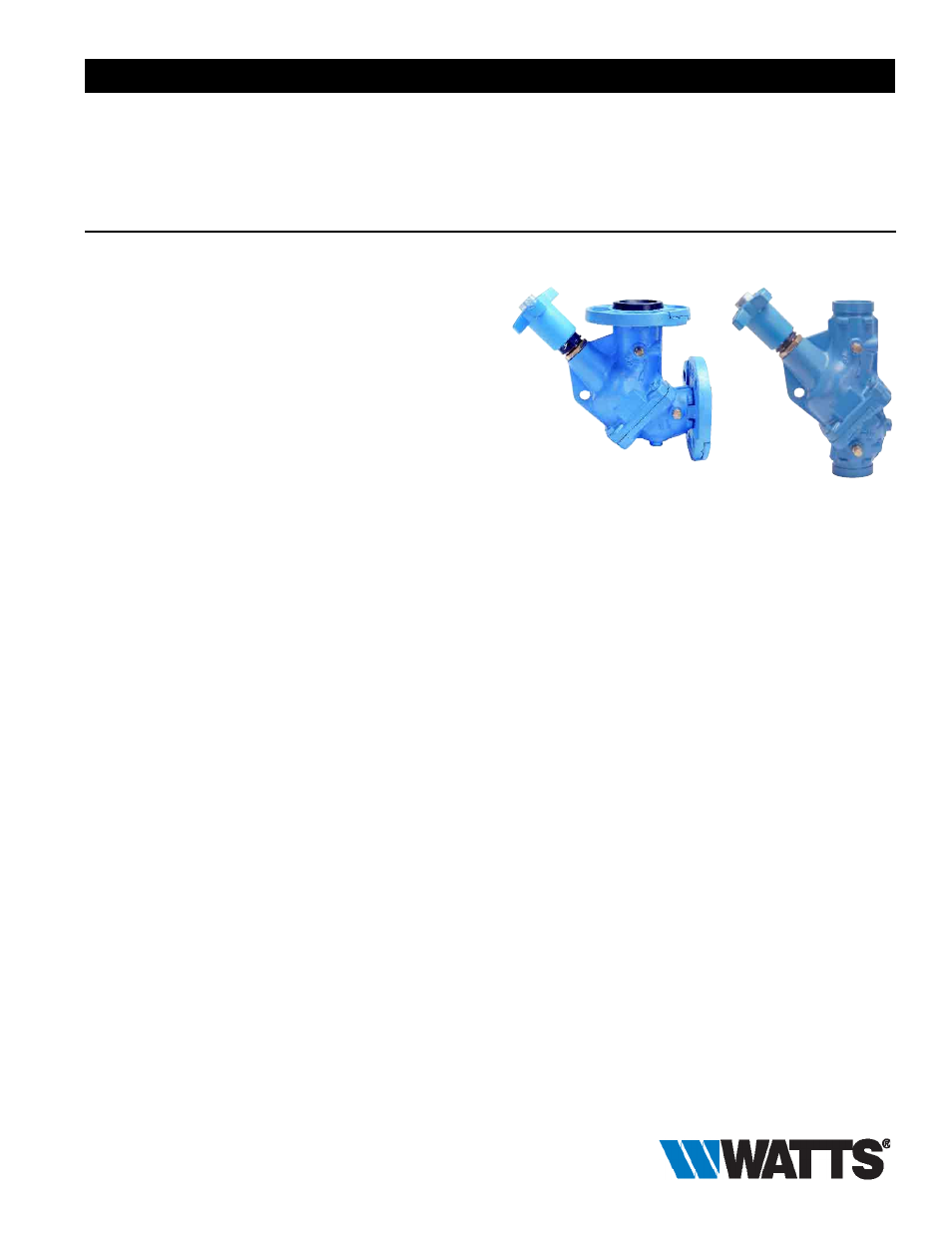
Series CSM-91 Flow Measurement/Balancing Valves are designed
for applications on medium or large flow rate HVAC systems, pump
packages, and cooling towers. They feature a multi-turn adjustment
range for maximum control. Pressure differential readout ports on
both sides of the valve to allow for easier installation and positive
shutoff for servicing equipment. In addition, these valves also incor-
porate a micrometer type handwheel adjustment, visually readable
settings and a tamper-proof memory stop.
The CSM-91’s field-convertible design allows the valve to be
changed from the factory-standard straight pattern to an optional
angle pattern with standard tools and no additional parts. This
allows the valve to be used as a replacement for angles or elbows
and will not affect the valve’s accuracy.
Maximum flow requires a one-foot pressure drop across the valve
to obtain an accurate meter reading with the valve set point from
50% to 100% open for greatest accuracy.
The valve should be installed with flow in the direction of the arrow
on the valve body, and installed at least five pipe diameters down-
stream from any fitting, and at least ten pipe diameters downstream
from any pump. Two pipe diameters downstream from the CSM-91
should be free of any fittings. When installed, easy and unobstructed
access to the valve handwheel and metering ports for adjustment
should be provided. Mounting of the valve in piping must prevent
sediment buildup in metering ports.
Features
• Multi-turn adjustment
• Interchangeable metering and drain ports on both sides
of valve
• Positive shutoff
• Tamper-proof memory stop
• Micrometer type handwheel adjustment - visually readable from
distance
• Field convertible for straight or angle pattern
• Grooved end connections with optional flange adaptors
Angle Pattern
Straight Pat tern
Specifications
A flow measurement valve shall be installed as shown on plans.
Each valve shall have two
1
⁄
4
” (6mm) NPT brass metering ports with
Nordel
®
check valves and gasketted caps located on both sides of
valve seat. Two additional
1
⁄
4
” (6mm) NPT connections with brass
plugs are to be provided on the opposite side of the metering ports
for use as drain connections. Drain connections and metering ports
are to be interchangeable for measurement flexibility when valves
are installed in tight locations. The valve body shall be ductile iron
with industrial standard grooved ends. Valve stem and plug disc
shall be bronze with ergonomically designed handwheel with multi-
turn handwheel adjustments. Sizes 2
1
⁄
2
” and 3” (65 and 80mm) -
five turns, 4” – 6” (100 – 150mm) - six turns, and 8” and 10” (200
and 250mm). Flange adaptors shall be supplied to prevent rotation.
The valve shall be a Watts Series CSM-91.
Pressure-Temperature
Grooved Ends Only
Maximum Working Pressure: 375psi (26.25 bar)
Maximum Temperature: 230°F (110°C)
Flange
Maximum Working Pressure:
Class 125: 175psi (12 bar)
Maximum Temperature: 230°F (110°C)
CSM-91
Nordel
®
is a registered trademark of DuPont Dow Elastomers.
Viton
®
is a registered trademark of DuPont Dow Elastomers.
Watts product specifications in U.S. customary units and metric are approximate and are provided for reference only. For precise measurements,
please contact Watts Technical Service. Watts reserves the right to change or modify product design, construction, specifications, or materials with-
out prior notice and without incurring any obligation to make such changes and modifications on Watts products previously or subsequently sold.
Job Name –––––––––––––––––––––––––––––––––––––––––––
Contractor ––––––––––––––––––––––––––––––––––––––––––––
Job Location –––––––––––––––––––––––––––––––––––––––––
Approval –––––––––––––––––––––––––––––––––––––––––––––
Engineer –––––––––––––––––––––––––––––––––––––––––––––
Contractor’s P.O. No. ––––––––––––––––––––––––––––––––––
Approval –––––––––––––––––––––––––––––––––––––––––––––
Representative ––––––––––––––––––––––––––––––––––––––––