D001, A001, Ff01-ff99 – Blizzard Lighting AW Rocklite (Rev A) User Manual
Page 9: Cc01-cc99, Deoo, Slav, Soud, B001
Page 12
ROCKLITE AW Manual Rev. A
Copyright (c) 2011 Blizzard Lighting, LLC
DMX Mode
Allows the unit to be controlled by any universal DMX controller. If you are unfamiliar with
DMX, please read the DMX Primer on page #15.
1.) The ROCKLITE RGBW is capable of operating with either 4 or 8 DMX chan-
nels. To use the fi xture in 4-channel mode, use the button to select
d001
on the LED Readout.
2.) To operate the fi xture in 8-channel mode, use the button to select
A001
on the LED Readout.
Stand-Alone, Master/Slave, Sound Active Modes:
Allows a single or Master/Slaved units to run factory installed programs at user selectable
speeds.
1.) To set the fi xture in Flash/Fade mode, select
FF01-FF99
(Fade Mode,
slowest to fastest) or
CC01-CC99
To confi rm, press the
2.) To use the fi xture in demo mode, select
dEoo
, then press the
button to confi rm.
3.) Each fi xture is a master by default. To set the fi xture as a slave, use the
button to reach
SLAv,
then press the
Sound Acitve Mode:
1.) To use sound active mode, select either
SouD
.
2.) Press the
Manual Mode (Color Preset Mode):
Allows a single unit to display a variety of colors without a DMX controller.
1.) Reach the manual adjustment by using the button to reach
b001
.
Adjust each color by using the
lect
r001-r255
,
g001-g255
,
b001-b255
or
u001-u255
(Red,
Green, Blue and White, respectively), and adjusting between 1 (lowest) and 255
(highest) for each color.
To confi rm, press the
Page 9
ROCKLITE AW Manual Rev. A
Copyright (c) 2011 Blizzard Lighting, LLC
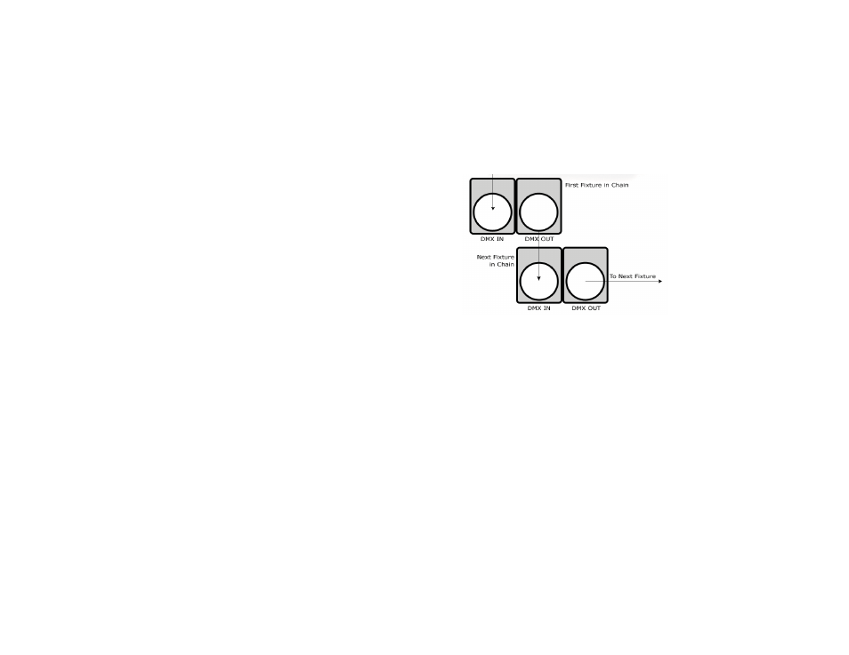
Fixture Linking (Master/Slave Mode)
1. Connect the (male) 3 pin connector side of the
DMX cable to the output (female) 3 pin connector of
the fi rst fi xture.
2. Connect the end of the cable coming from the
fi rst fi xture which will have a (female) 3 pin connec-
tor to the input connector of the next fi xture con-
sisting of a (male) 3 pin connector. Then, proceed
to connect from the output as stated above to the
input of the following fi xture and so on.
A quick note: Often,
the setup for Master-
Slave and Standalone
operation requires that
the fi rst fi xture in the
chain be initialized for
this purpose via either
settings in the control
panel or DIP-switches.
Secondarily, the fi xtures
that follow may also re-
quire a slave setting.
Check the “Operating Adjustments” section in this manual for com-
plete instructions for this type of setup and confi guration.
Mounting & Rigging
This fi xture may be mounted in any SAFE position provided there is
enough room for ventilation.
It is important never to obstruct the fan or vents pathway. Mount the
fi xture using a suitable “C” or “O” type clamp. The clamp should be
rated to hold at least 10x the fi xture’s weight to ensure structural sta-
bility. Do not mount to surfaces with unknown strength, and ensure
properly “rated” rigging is used when mounting fi xutres overhead.
Adjust the angle of the fi xture by loosening both knobs and tilting the
fi xture. After fi nding the desired position, retighten both knobs.
• When selecting installation location, take into consideration lamp
replacement access (if applicable) and routine maintenance.
• Safety cables MUST ALWAYS be used.
• Never mount in places where the fi xture will be exposed to rain,
high humidity, extreme temperature changes or restricted ventilation.