Tower top amplifier system – Bird Technologies 429-83H-01 Series-Datasheet User Manual
Page 2
Tower Top Amplifier System
429-83H-01-T, 429-83H-01-M
30303 Aurora Rd.
Solon, OH 44139
866.695.4569
www.bird-technologies.com
SYSTEMS SPECIFICATIONS
13 dB net gain and maximum 6 dB transmission line loss assumed
Bandwidth 792 – 824 MHz
System Noise Figure 2.9 dB Typ, 3.5dB Max
3rd Order IIP > 15 dBm
TTA Net Gain Fully settable by electronic attenuator
Filter Rejection 110 dB min, 120 dB nominal at 776 and 851 MHz
Net Weight 30.5 lbs for TTA + MCU
Ship Weight 42 lbs
TOWER TOP AMPLIFIER SPECIFICATIONS
All numbers are Typical unless stated otherwise
Frequency Range 792 – 824 MHz
Net Gain 23 dB
Noise Figure (Typ./Max) 2.7 dB / 3.0 dB
Backup Amplifier Switching Solid State RF Switch
Integrated Test Port Isolation 45 dB (Typ.)
Preselector Type
Loss
Rejection
7-pole TEM bandpass with cross-coupling
< 0.8 dB
> 60 dB @ 776 and 851MHz
LNA Type
Gain
Noise Figure
3rd Order Input IP:
2-stage Quadrature integrated into filter
26 dB
1.2 dB
+18 dBm
Impedance: 50 ohms
Antenna Port VSWR 2 :1
Power Requirements 12 VDC @ 1.25 A
Lightning Protection Impulse suppressor on all external connectors
Operating Temp Range -30°C to +60°C
Enclosure Modified NEMA 4X:
Stainless Steel Weather Resistant
Connectors N-Female
Dimensions (HWD) not including
mounting tabs or connectors
18” x 6” x 6” (457 x 152 x 152 mm)
Net Weight 20 lbs (9.1 kg)
MODEL NUMBERS
DESCRIPTION
89-83F-02-03
792-806 MHz, 3 MHz Bandwidth Preselector
89-83F-02-06
792-806 MHz, 6 MHz Bandwidth Preselector
89-83F-02-09
792-806 MHz, 9 MHz Bandwidth Preselector
89-83F-02-14
792-806 MHz, 14 MHz Bandwidth Preselector
89-86A-02-03
806-824 MHz, 3 MHz Bandwidth Preselector
89-86A-02-05
806-824 MHz, 5 MHz Bandwidth Preselector
89-86A-02-10
806-824 MHz, 10 MHz Bandwidth Preselector
89-86A-02-15
806-824 MHz, 15 MHz Bandwidth Preselector
Optional Filters:
Optional filters are available to provide a narrower window ahead of the
receiver multicoupler in order to achieve better selectivity for the system.
Please specify sub-band frequency when ordering
BASE UNIT SPECIFICATIONS MULTICOUPLER UNIT (MCU)
Frequency Range 792 – 824 MHz
Multicoupler Net Gain +1 dB typ; 0 dB min
Distribution Amp Type
Gain
Noise Figure
1dB Compression Point
3rd Order Output IP
Quadrature-Coupled Dual Stage
23 dB
4 dB
+27 dBm
+46 dBm
Number of outputs / Split Loss 16 or 32 / 18 dB
Impedence 50 ohms
VSWR < 2:1
Connectors: To TTA
To BTS
Test Port Input
N - female
BNC-female
BNC - female
Net Gain Electronic Attenuator 0-15.5 dB in 0.5 dB steps
Distribution Amp Electronic Attenuator 0~3 dB in 0.5 dB steps
Alarm and Warning Contacts Two Form C Contacts
(Nominal 2A @ 30 VDC or 0.5A @ 125 VAC)
I/O Ethernet
Power Requirements 90-240 VAC 50/60 Hz
180 mA @ 120 V or -48 VDC
(current draw is for base deck only, not
including the power needed to run
the tower top box).
Operating Temperature Range:
at non-condensing humidity
0°C to +50°C
Enclosure Standard EIA 19” Rack Mounting
Dimensions (HWD) 1 RU x 19” x 14” (38 x 483 x 356 mm)
Net Weight 10.5 lbs (4.8 kg)
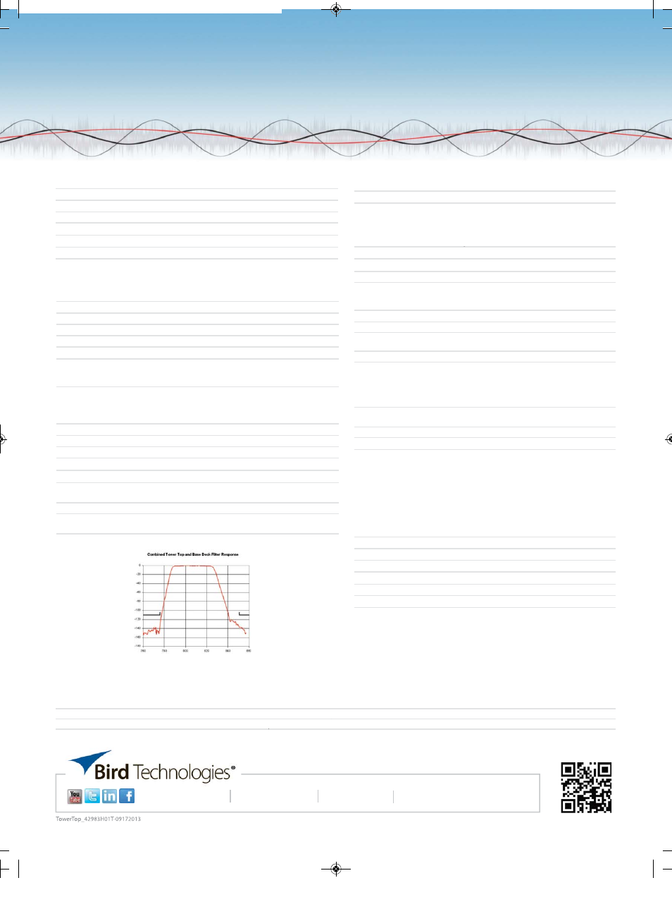
FREQUENCY (MHz)
A
T
TENU
A
TION
(
d
B
)
A steep skirted TEM bandpass filter in the tower box augmented by a ceramic filter in the base
unit provide a selective 32 MHz system window.
MODEL NUMBERS
DESCRIPTION
POWER REQUIREMENTS
429-83H-01-T
TTA, 792-824 MHz, Tower Top Box only
429-83H-01-M
Receiver Multicoupler for TTA, 16-Port, 792-824 MHz
AC
429-83H-01-M-48
Receiver Multicoupler for TTA, 16-Port, 792-824 MHz
DC
TowerTop_42983H01T_2012 branding 9/17/2013 10:56 AM Page 2