Video output connector, User controls, Installation – AJA HD10C2 User Manual
Page 6: User controls installation
HD10C2 Mini-Converter v1.0r2
www.aja.com
6
Video Output
Connector
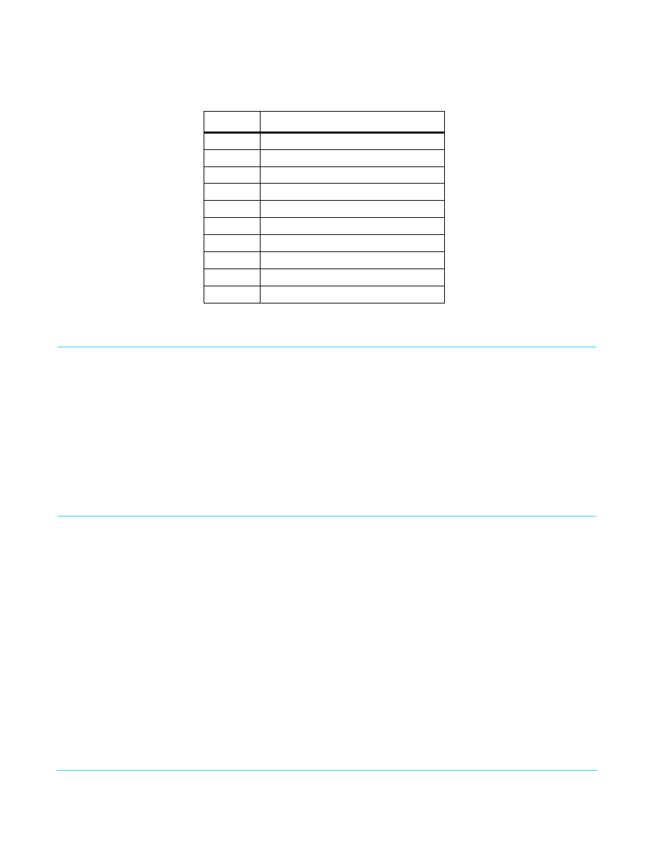
The video output connector is a 13W3 D-sub with the following pinouts:
User Controls
The user interface for the HD10C2 is an 8-switch DIP accessible through a cut-out in the
bottom of the unit, and an internal jumper block accessed by removing the converter’s
cover (secured by 4 screws).
Use the jumper to configure HD Sync, if necessary. Then use the DIP switches to
configure the converter.
Factory default settings are internal jumper installed (HD uses Tri-level Sync), and all the
DIP switches in the leftmost position. The exact function of the jumper settings and each
DIP switch are described in
.
Installation
Typically, HD10C2 installation consists of the following:
1. Disconnect +5VDC from the converter.
2. If you wish to operate the HD10C2in HD with Bi-level Sync, open the case and set the
internal jumper as required.
3. Configure the DIP switches for the desired settings.
4. Connect external devices to the converter BNCs and breakout cable or VGA adapter.
5. Apply power to the converter.
Table 1. Video Output Connector Pinouts
Pin
Description
1
no connection
2
V DRIVE
3
no connection
4
GROUND
5
H DRIVE
6 - 9
no connection
10
GROUND
A1
RED / Pr Video/ C
A2
GREEN / Y Video / Composite
A3
BLUE / Pb Video / Y