Bell & Gossett P81875G Series HSC-S Centrifugal Pump User Manual
Page 18
1. Mechanical Seals on Shaft
DISASSEMBLY
NOTICE: Numbers that appear in parenthesis ( ), such as
Ê
(1-939-9), may be used to order replacement parts.
Ê
1. Close valves on suction and discharge sides of pump. (If
Ê
no valves have been installed, it will be necessary to drain
Ê
the system.)
Ê
1
nÊ
CAUTION: Extreme Temperature Hazard
Allow pump temperatures to reach acceptable levels
Ê
before proceeding. Open drain valve, do not proceed until
Ê
liquid stops coming out of drain valve. If liquid does not
Ê
stop flowing from drain valve, isolation valves are not seal-
Ê
ing and should be repaired before proceeding. After liquid
Ê
stops flowing from drain valve, leave drain valve open and
Ê
continue. Remove the drain plug located on the bottom of
Ê
the pump housing. Do not reinstall plug or close drain
Ê
valve until reassembly is completed. Failure to follow these
Ê
instructions could result in property damage and/or moder-
Ê
ate personal injury.
Ê
WARNING: Unexpected Start-up Hazard
Disconnect and lock out power before servicing.
Ê
Failure to follow these instructions could result in serious
Ê
personal injury or death and property damage.
Ê
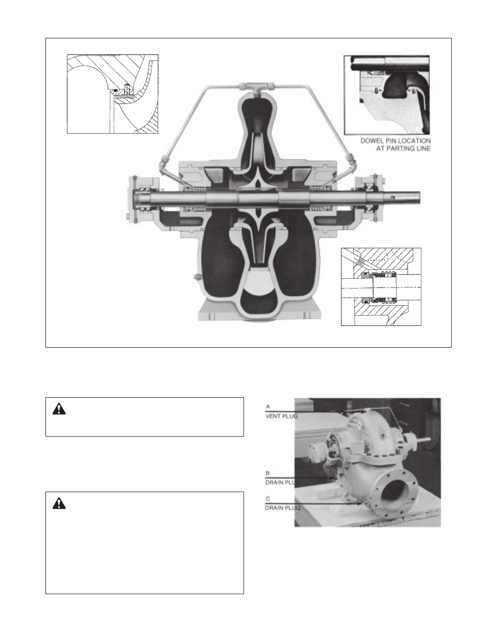
Photo 1 – Assembly Section: Pump With Mechanical Seals on Shaft
Photo 2 – Pump with Mechanical Seals
Impeller rings can be added–
Optional Extra.
IMPELLER WEAR RING
Optional Extra.
BALANCED
MECHANICAL SEAL
NOTE:
Standard mechanical seal pip-
ing can be modified for filter or
external flushing arrangement.