Audio-Technica ATW-T210A User Manual
Page 4
2000 Series Installation and Operation
4
Receiver Controls and Functions
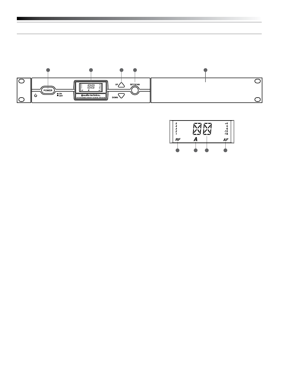
Fig. B
– Front Panel Controls and Functions
1. POWER SWITCH: Press the Power switch in to turn the receiver
on. The LCD window will light, and the operating channel number
will be displayed in the window. To turn the receiver off, press the
Power switch again.
2. LCD WINDOW: Liquid Crystal Display indicates channel setting and
operational readings. See Fig. C for examples.
3. UP/DOWN BUTTONS: Press Up or Down arrow buttons to arrive at
desired channel. The selected number will flash on and off. Press
and hold Set/Scan button to set the channel (operating frequency).
4. SET/SCAN BUTTON: Two distinct operations are associated with
this button:
Touch: A momentary press of the Set/Scan button.
Hold: A press and hold (about two seconds) of the Set/Scan button.
The Set/Scan button can be used in two ways: Manual Set Mode,
to permit selection of an operating channel; and Automatic Scan/Set
Mode, to initiate the automatic channel scan and selection, as follows:
Manual Set Mode: After using the Up or Down arrow button to
arrive at desired channel, hold the Set/Scan button to set the
channel. NOTE: Before the channel has been set, a touch of the
Set/Scan button will revert the channel to its previous setting.
Automatic Scan/Set Mode: Hold the Set/Scan button. The Automatic
Scan/Set Mode will automatically scan for and set the next open
channel.
5. MOUNTING ADAPTERS: For mounting the receiver in any standard
19" rack. Attach adapters to the receiver with the screws supplied
and remove the four receiver feet. (Use optional AT8630 joining-
plate kit to mount two ATW-R2100a receivers side-by-side.)
Fig. C
– Receiver LCD Window Display
6. RF SIGNAL LEVEL INDICATOR: Shows the strength of the RF signal
received from the transmitter.
7. TUNER OPERATION INDICATOR: Indicates which Tuner (A or B) has
the better reception and is in operation.
8. CHANNEL DISPLAY: Shows which channel is selected.
9. AF LEVEL INDICATOR: Shows the audio modulation level of the
received signal.
1
2
3
4
5
6
7
9
8