Warning, Wiring – Proface GP4100 - 3.4 Compact HMIs" User Manual
Page 5
5
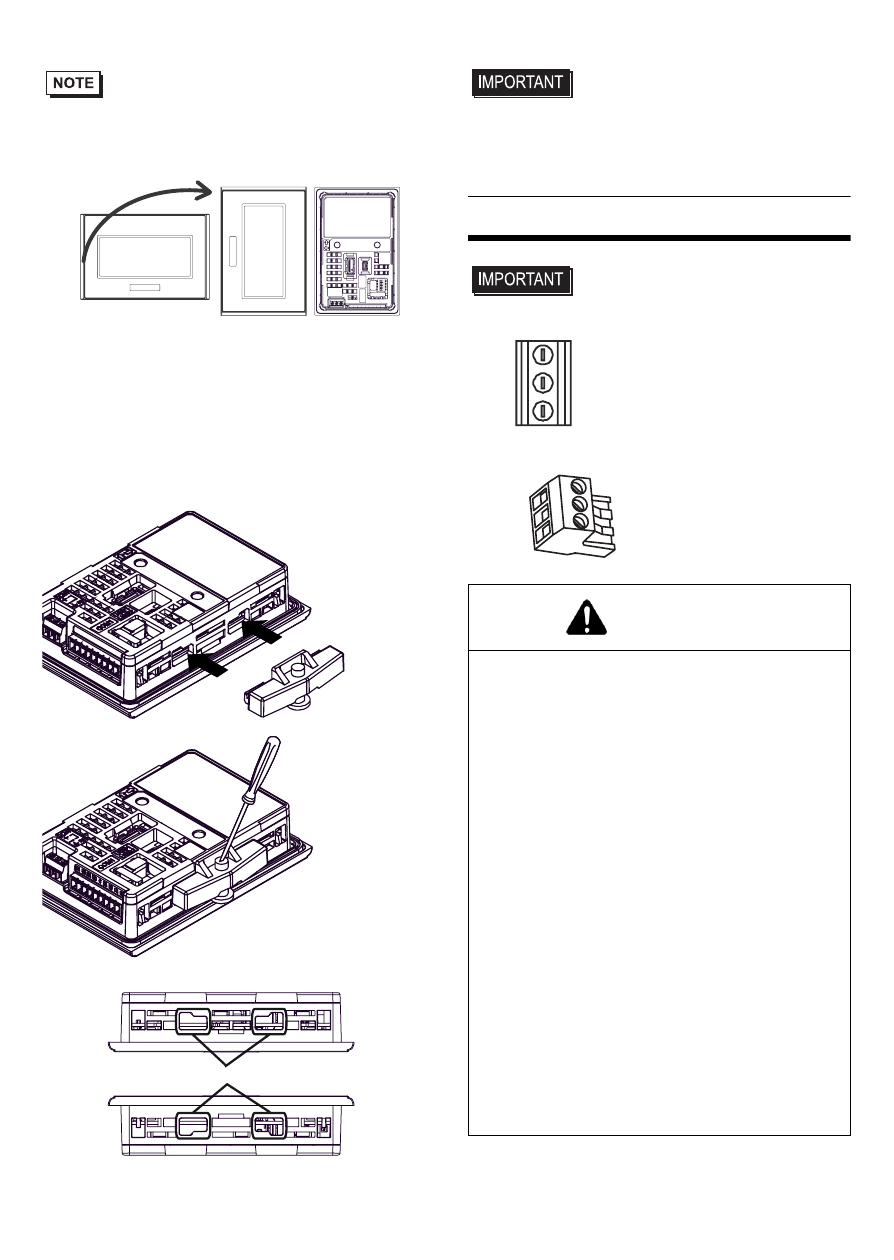
• When mounting the GP unit vertically, ensure that
the left side of the unit faces up (i.e. the power
connector and serial interface should be at the
bottom).
(3) Press the installation fastener hooks securely
into the insertion slots on the GP unit. (Press
the hooks in again to release the lock and
remove the installation fasteners.)
(4) Tighten the installation fasteners with a screw-
driver. There are two insertion slots on both the
top and bottom of the GP unit.
• Tightening the screws with too much force can
damage the GP unit’s plastic case.
• In order to guarantee water repelling effect the
necessary torque is 0.52N
•m [4.60Lb•in].
Wiring
• If the power connector is the following type,
please read "1. Wiring the Power Cord No.1".
• If the power connector is the following type, please
read "2. Wiring the Power Cord No.2".
Mounted
Horizontally
Front and Rear Views
when Mounted
(3)
Press the hooks
securely into
the insertion
slots.
(4)
Tighten the
screw with a
screwdriver
Top
Bottom
Insertion Slots
WARNING
HAZARD OF ELECTRIC SHOCK
•
Prior to connecting the GP unit's power cord
terminals to the power terminal block, confirm
that the GP unit's power supply is completely
turned OFF, via a breaker, or similar unit.
•
Supplying a power voltage other than that
specified will damage the power source and
the GP unit.
•
Since there is no power switch on the GP
unit, be sure to attach a breaker-type switch
to its power cord.
•
When the FG terminal is connected, be sure
the wire is grounded.
Failure to follow these instructions will result
in death or serious injury.