Pumptec 207V SERIES User Manual
Page 8
8
Version 110112
Pumptec Operating Instructions and Parts Manual
PUMP SERIES 205V | 207V
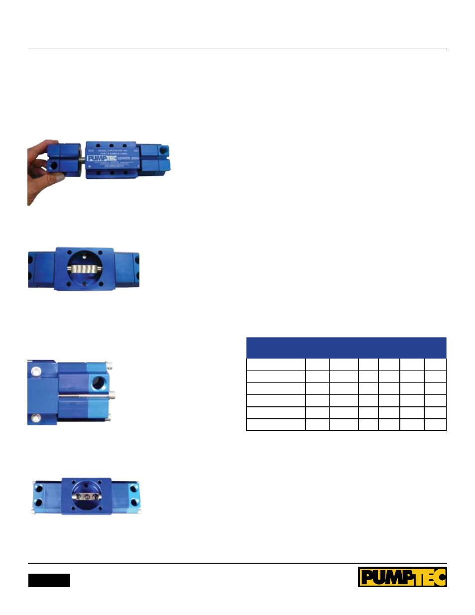
10. Hold head and stuffing box assembly and slide onto plunger
at one end. Plunger may require to be held in place. Repeat
with other head and stuffing box. Center plunger slot in
crankcase when finished. Figure 9, on shows putting head and
stuffing box assemblies on plunger.
Figure 9
Figure 10 shows head and stuffing box assembled.
Figure 10
11. Place bolts into bolt slot at each end and tighten, DO nOT
tighten completely at this time. Move plunger back and forth
two times and then tighten bolts to 14 in/lbs. of torque. Figure
11 shows installing bolts at each end.
Figure 11
12. Apply black grease from supplied packet into corners and
center of plunger slot.
Figure 12
13. Mount pump back onto motor and tighten mounting bolts
to 14 in/lbs. of torque.
LuBRiCAtiON
Apply 1.5 oz of suppliers black grease to the corners and center
of plunger slot at the time of service.
StorINg
For extended storing, or between use in cold climates, drain all
pumped liquids from pump and flush with antifreeze solution
to prevent freezing and damage to the pump. DO nOT RUn
PUMP WITH FROZEn lIQUID.
Note:
Each system’s maintenance cycle will be unique. If
system performance decreases, check immediately. If no wear
at 500 hours, check again at 1000 hours and each 500 hours
until wear is observed. Valves typically require changing every
seal change. Duty cycle, temperature, quality of pumped liquid
and inlet feed conditions all effect the life of a pump’s wear
parts and service cycle.
Note:
Remember to service the regulator/uploader at each
seal servicing and check all system accessories and connections
before resuming operation.
PREVENtiVE mAiNtENANCE CHECkLiSt
Check
daily weekly 50
Hrs.
500
Hrs.
1500
Hrs.
3000
Hrs.
Clean Filters
X
Water leaks
X
Descale Pump
X
X
Cam & bearing
X
X
Seal Change
X
X
Valve Change
X
X