Pumptec 207V SERIES User Manual
Page 7
7
Version 110112
Pumptec Operating Instructions and Parts Manual
PUMP SERIES 205V | 207V
MAINteNANce
DISASSEMblY AnD REASSEMblY
InSTRUCTIOnS (Refer to Schematic)
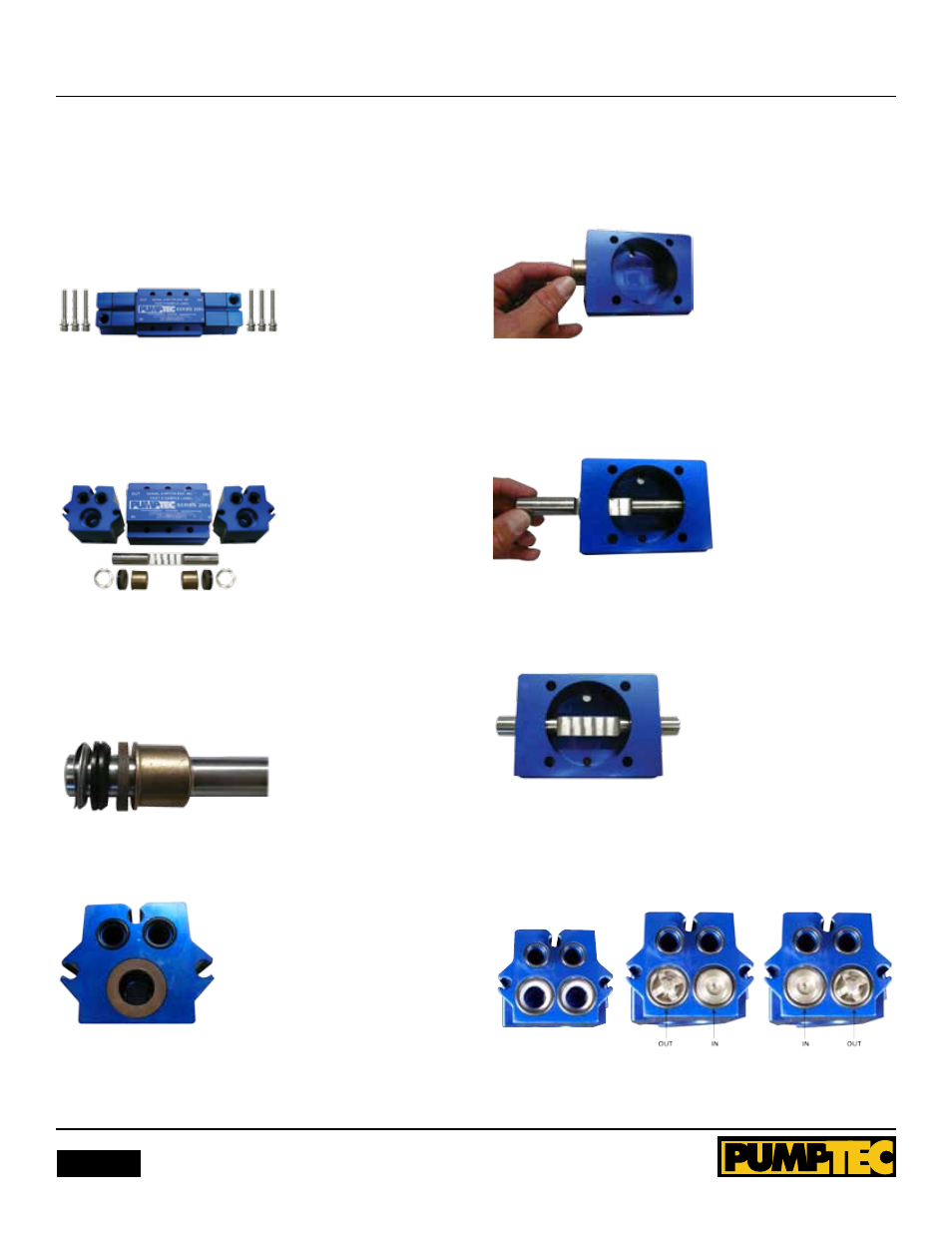
1. Remove pump from motor using a 3/16” hex wrench.
Remove bolts at each end of pump. Figure 1 shows pump
separate from motor with manifold facing upward and bolts set
to side.
Figure 1
2. Holding head and stuffing box at each end pull them apart
to remove plunger. Remove guides from crankcase. Remove
internal seal parts with finger. Discard parts. Figure 2 shows
pump ends pulled apart showing plunger, crankcase, guides and
internal seals removed.
Figure 2
3. Clean the stuffing box and crankcase with a rag or towel.
Inspect for damage or excess corrosion. If the stuffing box is
damaged, do not rebuild. note the order and orientation of
repair parts prior to installation. Figure 3 shows repair parts in
order and in correct orientation.
Figure 3
4. Place one wave washer, one spreader, two V-packings and
one backing ring into bore. Figure 4 shows parts in bore.
Figure 4
5. Repeat the previous steps 2-4 with the other stuffing box.
6. Place one guide at each end of crankcase. guides should
be loose and easily slide in. Figure 5 shows placing guides into
crankcase.
Figure 5
7. lightly grease the plunger with clear grease provided in small
grey tube. Slide plunger through plunger guides in crankcase.
Figure 6 shows plunger in crankcase.
Figure 6
8. Adjust plunger slot position towards center and have slot
facing work surface. Figure 7 shows plunger slot positioning.
Figure 7
9. Replace all valves, O-rings and 1/2” ID white washers. Refer
to image and manifold label to understand proper orientation.
Figure 8 shows proper orientation with valves and O-rings in
place.
Figure 8
PROPER AlIgnMEnT