3 minimum flow values -10, Refer to sections 5-3 and 5-4 f, W listed in table 5-3 – Brooks Instrument 5866M User Manual
Page 33: W listed in table 5-3 go to, Alues listed in table 5-3, W listed in table 5-3 the v, W listed in table 5-3 decrease the
Brooks Instrument Model 5866 Pressure Controller
5-10
B. Adjustment procedure, Normally Open (N.O.) control valve
Refer to Figure 5-4 for spacer locations and nomenclature for the Normally
Open (N.O.) type control valve. Refer to Section 7, spare parts for the
spacer part numbers and the spacer kit part number. The valve clearance
determines the maximum space between the orifice (12) and the valve
seat (11). If the valve clearance is too small the controller will not achieve
full flow. If the valve clearance is too large, the control valve will not close
properly.
The air gap is the space between the plunger (16) and insert (17) in the
control valve. The air gap determines the magnetic force available to
operate the valve. If the air gap is too large the magnetic force will be
insufficient and the valve will not close. If the air gap is too small the valve
will have insufficient travel and the valve will not close.
1. Make the bench testing set up as shown in Figure 5-2. Disconnect the
valve connector from the side of the Model 5866 and connect it to the
variable power supply and volt meter as shown. Polarity is not important.
2. Remove gas pressure. Disassemble the control valve following the
procedure given in Section 5-3, above. Note the orifice size, which is
marked on the orifice face. Referring to Figure 5-4, note the number,
location and thickness of all spacers (9 and 10).
3. Reassemble the valve and set the variable voltage power supply to zero
Volts.
4. Apply 5 psig to the inlet of the Model 5866 if equipped with 0-1 bar
transducer. Apply 10 psig for instruments equipped with other
transducers.
5. Observe the flow and compare it to the values listed in Table 5-3.
6. If the observed flow is greater that the listed value for the orifice size
that is installed then go to Step 8.
7. If the flow is less than the minimum flow increase the valve clearance
by adding a large 0.005" spacer (10) above the spring spacer (19) and
repeat Steps 5 and 6.
8. Apply 18 Volts to the valve using the variable power supply and observe
the flow.
Note: The maximum allowable leak through in controllers with an
elastomer valve seat is 2% of the values listed in Table 5-3, (multiply by
0.02). The maximum allowable leak through for controllers with a metal
or Teflon valve seat is 8% of the values listed in Table 5-3, (multiply by
0.08).
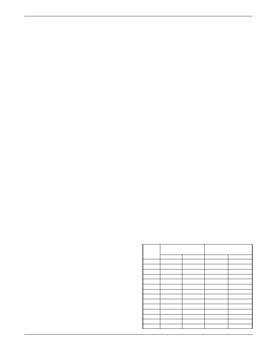
Table 5-3. Minimum Flow Values.
Orifice
Minimum Flow
Minimum Flow
Size
with 10 psig pressure
with 5 psig pressure
(inches)
sccm (0°C) sccm (70°F) sccm (0°C)
sccm (70°F)
.001
5.3
5.7
3.9
4.0
.002
12.5
13.5
8.8
9.5
.003
39.2
42.2
27.7
29.8
.004
82.5
88.9
58.5
62.9
.007
374
403
264
285
.010
748
806
529
570
.014
1,364
1,470
964
1,039
.020
2,673
2,879
1,890
2,040
.032
6,490
7,000
4,590
4,940
.048
13,000
14,000
9,180
9,890
.062
22,000
23,700
15,500
16,800
.078
31,900
34,400
22,500
24,300
.093
42,500
45,800
30,000
32,400
.120
69,300
74,700
49,000
52,800