Adjusting the control valve -6, 1 torque sequence for the valve retainer plate -6, Dure and/or section 5-5 – Brooks Instrument 5866M User Manual
Page 29: Adjust valve. refer to section 5-5
Brooks Instrument Model 5866 Pressure Controller
5-6
4. Install the orifice (12) and its O-ring (13) using a 3/8" nut driver. Insure
that the orifice is fully seated but do not overtighten.
5. Insert the valve preload spacers (10), if used, into the valve cavity in the
controller body (25). Use care to preserve the correct order.
6. Install the valve plunger assembly (7, 8, 9 and 11) on the preload
spacers (10). Install air gap spacers, if used, on top of the valve
springs.
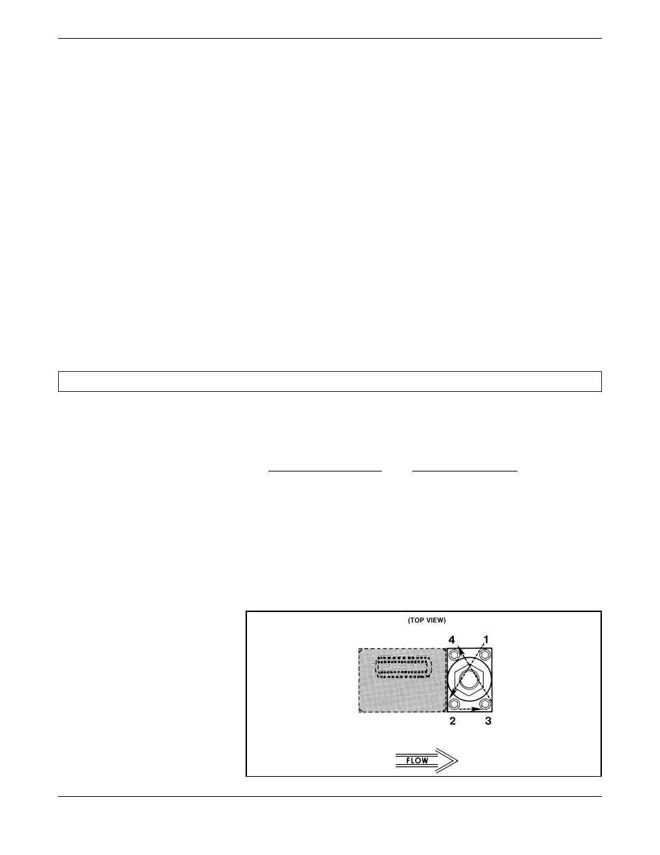
7. Install the valve stem assembly (6), secure with the valve retaining plate
(4) and four hex socket screws (3). When installing the screws, insure
that the plate makes full contact all the way around the stem. Torque the
screws, securing the retaining plate in a diagonal pattern (refer to
Figure 5-1) to 15 in-lbs.
8. Install the coil assembly (2) over the valve stem assembly (6) and
secure with jam nut (1).
9. Install the printed circuit board (30), secure with the bracket (28) and
two screws (29). Plug the connector from the sensor onto the printed
circuit board.
10.Install the electronics cover (31) on the controller, secure with three
screws (29) and two standoffs (33). Plug the connector from the valve
coil into the printed circuit board through the hole in the electronics
cover.
11.Prior to installation, leak and pressure test the controller to any
applicable pressure for the transducer (refer to Section 4-1).
5-5 Adjusting the Control Valve [numbers in ( ) refer to Figure 7-1]
The Model 5866 control valve has been factory adjusted to insure proper
operation. Adjustment is not normally required during the life of the
instrument. Readjustment may be required if any of the following parts
have been replaced:
Normally Closed Valve
Normally Open Valve
Orifice (12)
Orifice (12)
Valve Stem (6)
Valve Stem (15)
Plunger (7)
Plunger (16)
Lower Guide Spring(s) (8)
Lower Guide Spring (8)
Valve Seat (11)
Valve Seat (11)
Downstream Control
Downstream Control
Adaptor (21)
Adaptor (21)
Plunger Extension (18)
Spring Spacer (19)
Insert Sleeve (17)
Figure 5-1. Torque Sequence for
the Valve Retainer Plate.