Table 27 - ecm condenser fan cycling options – AAON RN-140 User Manual
Page 80
80
Condenser Fan Electronically
Commutated Motor (ECM) Startup
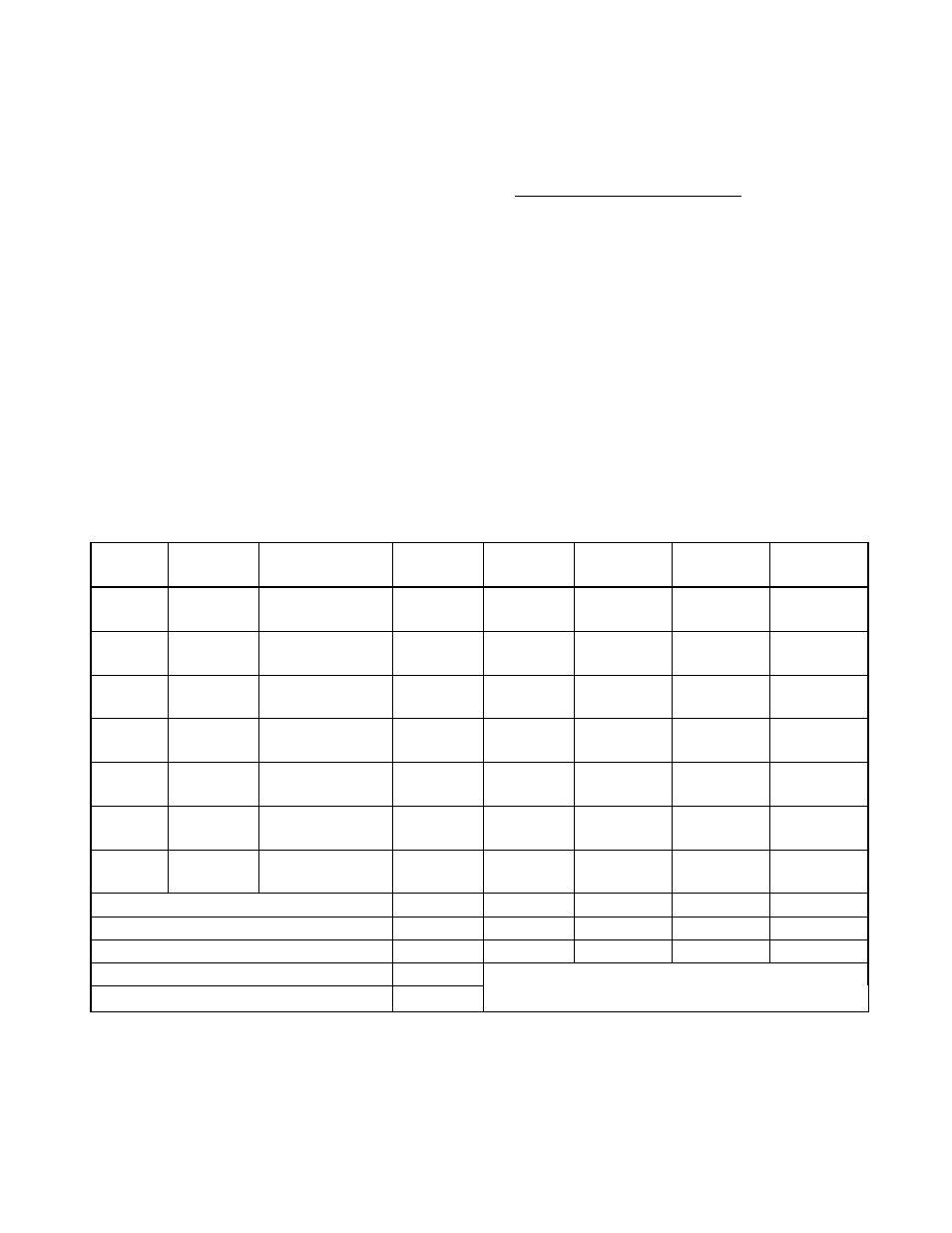
The fan cycling option uses a fan cycle
switch to switch between one of the discrete
speed inputs (see Table 27) on the motor
thus cycling between two preset speeds
based upon discharge pressure of the unit.
By connecting 24VAC to a single or
combination of the yellow, white, or orange
wires, the motor will run at the discrete
speeds in Table 27.
With Customer Provided Unit Controls or
WattMaster Unit Controls the WattMaster
Condenser Head Pressure Module is used
for variable speed control of the motor to
maintain a head pressure. The motor should
be factory wired to the PWM outputs of the
WattMaster
Condenser
Head
Pressure
Module. See WattMaster literature for
further information.
With JENEsys Unit Controls the controller
modulates the ECM to maintain head
pressure.
Note
High voltage wires out of the motor:
Black & Brown - 1 Phase Line Voltage
Green - Ground
Low control voltage wires out of the motor:
Blue - Common
Yellow - Variable Speed Control
Table 27 - ECM Condenser Fan Cycling Options
Color
Terminal
Customer
Connection
Option 1
Option 2
Option 3
Option 4
Option 5
Black
0.50
BWS
L1
208-230
VAC
208-230
VAC
208-230
VAC
208-230
VAC
208-230
VAC
Brown
0.50
BWS
L2
208-230
VAC
208-230
VAC
208-230
VAC
208-230
VAC
208-230
VAC
Green
#10
EYELET
Ground
GND
GND
GND
GND
GND
Blue
0.50
BWS
Common
Common
24 VAC
24 VAC
24 VAC
24 VAC
Yellow
0.50
BWS
Signal
PWM
24 VAC
24 VAC
White
0.50
BWS
Signal
24 VAC
24 VAC
Orange
0.50
BWS
Signal
24 VAC
24 VAC
RPM 300-1100
300
500
850
1100
Rotation
CCW
CCW
CCW
CCW
CCW
ECM Toolbox ID
Variable
Speed 4
Speed 3
Speed 2
Speed 1
20% PWM RPM
300
100% PWM RPM
1100