I-View CP-4800DX Hybrid DVR Card User Manual
Page 3
3
1
2
3
Fig 10
it will cause the sensor damage.
2. Make sure that the sensor itself is not covered and is facing the place from where you will be using the
remote controller.
3. Make sure that the sensor itself plug into the phone jack completely.
4. The system allows to extent sensor cable (Fig 5) for control the TV out from far away site via Remote
Controller. Please follow the process as below to achieve this function:
a. Please use the shading cable such as 28#2C+S type.
b. The sensor cable includes 3-wire cable: Red (DC 5V), Shading cable (Ground), White (Signal).
c. If the extension sensor cable too far away DVR and needs extra DC5 V power for the sensor,
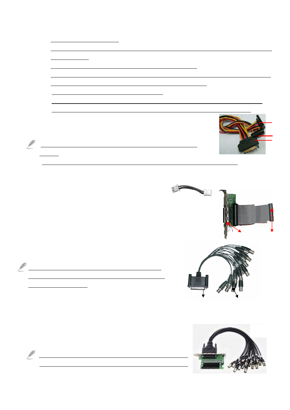
(E) Power Cable (Fig 6)
Plugged “ 1 “ port to the power supply of PC, the other “2” or “3 “ ends should be
connected to CP-4800DX.
1. Must provide the power for the CP-4800DX Pro, otherwise cannot work
properly.
2. Do not share power for the other devices for each power line when connected CP-4800DX.
(F) Linking cable (Fig 7) CP-4800DX XP 1 only
The Linking cable on the package CP-4800DX XP 1 to connect the port between the (3) port of CP-4800DX
XP 0 and (6) port of CP-4800DX XP 1.
(G) Audio Board (Optional) as shown in “Fig 8 ”
Connector the “1 “of the Fig 8 with a DB-25 pins audio connector
(as shown in Fig 10) for the audio inputs.
Plug the “2” of the Fig 8 into the “14” Audio-in socket of the DVR card.
(H) Audio Cable (Option) as shown in “Fig 9”.
Connect the DB-25 Pin connector to the Audio Board (As Fig 9).
Connect the 16 BNC audio connectors for the audio inputs.
The mark “A” on the BNC connector’s means “ Audio input”.
The mark “A1” on the BNC video connector means “Audio 1”,
“A2” means “Audio 2” etc.
(I) Video Looping Board and cable (Optional) as shown in “Fig 10 ”
Using flat cable to connect the video looping board and CP-4800DX DVR card.
Plug DP-25 pin BNC cable to Video looping board
Connector the “1 “of the Fig 10 with a DB-25 pins audio connector
The BNC connector will provide 16 video output signal.
The mark “V” on the BNC connector’s means is the mark “V1” on
the BNC video connector means “Video1”, “V2” means “Video 2”…
(Fig 6)
(Fig 8)
1
2
(Fig 7)
DB-25 Pin
(Fig 9)
BNC Audio
Connectors