Applications information, Table 2. high-frequency boost for each mode, Table 3. gain setting control – Rainbow Electronics MAX7445 User Manual
Page 6: Table 4. output clamp level
MAX7445
4-Channel Video Reconstruction Filter
6
_______________________________________________________________________________________
High-Frequency Boost
The high-frequency boost available on the CVBS, Y, and
C video channels increases image sharpness by com-
pensating for signal degradation and roll-off in the video
encoder. Table 2 shows the channels that have the high-
frequency boost option for the three operating modes.
The channels without high-frequency boost have a flat
response over the video bandwidth.
Output Buffers
Each output buffer can drive two 150
Ω video loads with
a 2V
P-P
signal. The output buffer gain is selectable
between +6dB, +9.5dB, or +12dB by using GAIN (see
Table 3). The MAX7445 can drive an AC load or drive
the video load directly without using a large output
capacitor. The output buffers drive DC loads with an
output blanking level of less than 1V.
12dB Gain Setting
GAIN is biased internally to V
CC
/ 2 with a resistor-
divider pair of 100k
Ω resistors from V
CC
to GND such
that the internal impedance at the node is 50k
Ω. No
additional connection is necessary since the input
offers a minimum noise-margin immunity of 1V
P-P
.
Output Clamp Level
When sync pulses are detected in either a CVBS or G
video signal, the DC restore loop is activated. The func-
tion of the loop is to set the DC level of the video signal
to a specified voltage. See Table 4 for clamp levels.
Applications Information
Input Considerations
Use 0.1µF ceramic capacitors to AC-couple the inputs.
These input capacitors store a DC level so the outputs
are clamped to an appropriate DC voltage level.
Output Considerations
The outputs are typically connected to a 75
Ω series
back-match resistor followed by the video cable.
Because of the inherent divide-by-two of this configura-
tion, the voltage on the video cable is always less than
1V, complying with industry-standard video require-
ments such as the European SCART standard (which
allows up to 2V of DC on the video cable). The video
buffer can also drive an AC-coupled video load. Good
video performance is achieved with an output capacitor
as low as 220µF.
Power-Supply Bypassing and Layout
The MAX7445 operates from a single +5V supply.
Bypass V
CC
to GND with a 0.1µF capacitor. Place all
external components as close to the device as possible.
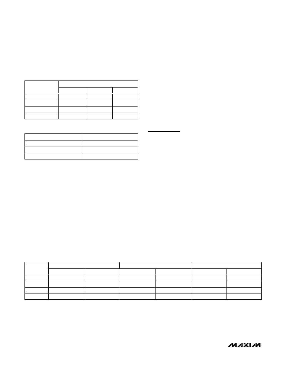
Table 2. High-Frequency Boost for Each
Mode
HIGH-FREQUENCY BOOST (dB)
CHANNEL
MODE 1
MODE 2
MODE 3
A
+1.2
+1.2
–
B
–
+1.2
–
C
–
+1.2
–
D
–
+1.2
+1.2
Table 3. Gain Setting Control
GAIN
BUFFER GAIN (dB)
GND
+6
V
CC
+9.5
Floating
+12
Table 4. Output Clamp Level
MODE 1: SELECT = GND
MODE 2: SELECT = V
CC
MODE 3: SELECT = FLOATING
CHANNEL
CLAMP LEVEL (V)
SYNC SOURCE
CLAMP LEVEL (V)
SYNC SOURCE
CLAMP LEVEL (V)
SYNC SOURCE
A
0.8
Channel A
0.8
Channel A
0.8
Channel A
B
1.4
Channel A
0.8
Channel A
1.4
Channel A
C
1.4
Channel A
1.6
Channel A
1.4
Channel A
D
1.4
Channel A
0.8
Channel D
0.8
Channel D