Gas connection – United States Stove Company 2020N User Manual
Page 12
GAS CONNECTION
CAUTIONCAUTIONCAUTIONCAUTIONCAUTION
Use new black iron or steel pipe only. Internally tinned copper tubing can be
Use new black iron or steel pipe only. Internally tinned copper tubing can be
Use new black iron or steel pipe only. Internally tinned copper tubing can be
Use new black iron or steel pipe only. Internally tinned copper tubing can be
Use new black iron or steel pipe only. Internally tinned copper tubing can be
used in some areas when permitted by local codes. Only use pipe of 1/2" or
used in some areas when permitted by local codes. Only use pipe of 1/2" or
used in some areas when permitted by local codes. Only use pipe of 1/2" or
used in some areas when permitted by local codes. Only use pipe of 1/2" or
used in some areas when permitted by local codes. Only use pipe of 1/2" or
greater diameter to allow full gas volume to heater. Excessive pressure loss will
greater diameter to allow full gas volume to heater. Excessive pressure loss will
greater diameter to allow full gas volume to heater. Excessive pressure loss will
greater diameter to allow full gas volume to heater. Excessive pressure loss will
greater diameter to allow full gas volume to heater. Excessive pressure loss will
occur if the pipe is too small.
occur if the pipe is too small.
occur if the pipe is too small.
occur if the pipe is too small.
occur if the pipe is too small.
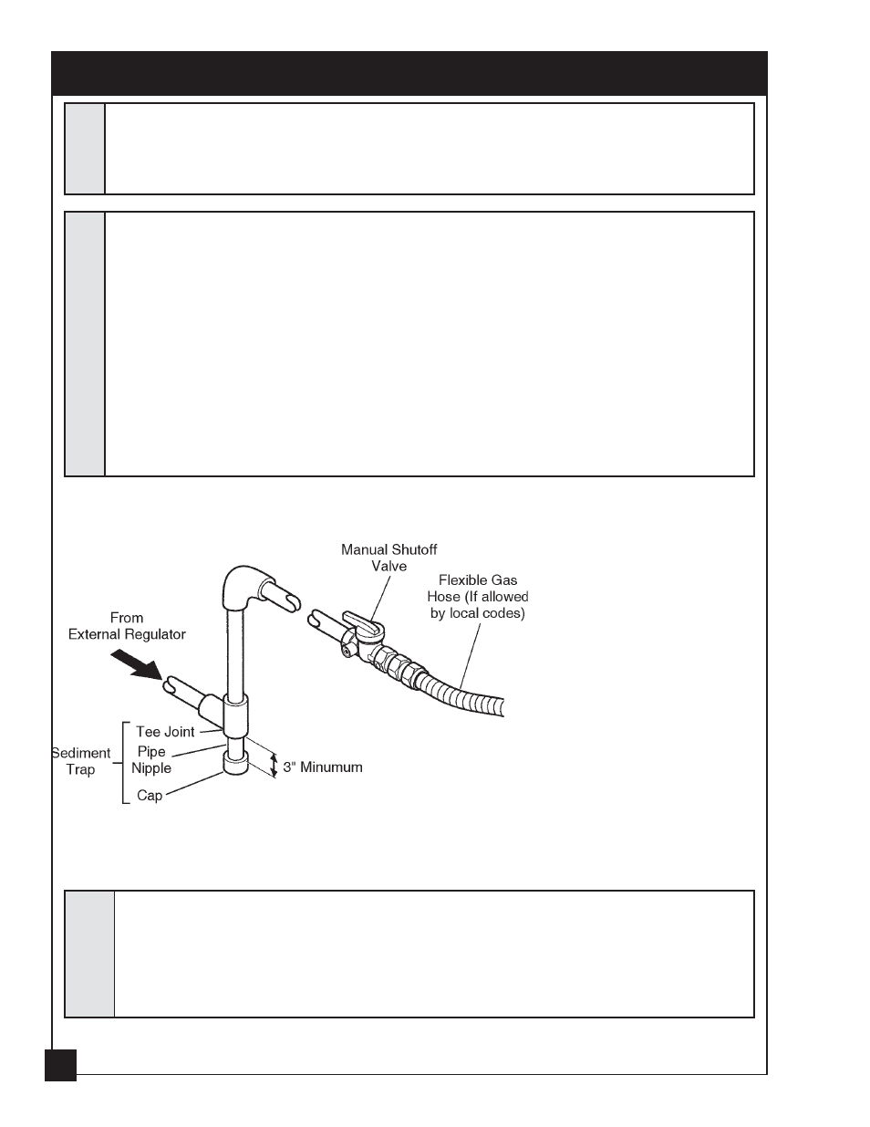
A manual shutoff valve, union and plugged 1/8" NPT pressure tapping point
A manual shutoff valve, union and plugged 1/8" NPT pressure tapping point
A manual shutoff valve, union and plugged 1/8" NPT pressure tapping point
A manual shutoff valve, union and plugged 1/8" NPT pressure tapping point
A manual shutoff valve, union and plugged 1/8" NPT pressure tapping point
must be installed upstream of the heater (FIGURE 8).
must be installed upstream of the heater (FIGURE 8).
must be installed upstream of the heater (FIGURE 8).
must be installed upstream of the heater (FIGURE 8).
must be installed upstream of the heater (FIGURE 8).
A sediment trap must be installed upstream of the heater to prevent moisture
A sediment trap must be installed upstream of the heater to prevent moisture
A sediment trap must be installed upstream of the heater to prevent moisture
A sediment trap must be installed upstream of the heater to prevent moisture
A sediment trap must be installed upstream of the heater to prevent moisture
and contaminants from passing through the pipe to the heater controls and
and contaminants from passing through the pipe to the heater controls and
and contaminants from passing through the pipe to the heater controls and
and contaminants from passing through the pipe to the heater controls and
and contaminants from passing through the pipe to the heater controls and
burners. Failure to do so could prevent the heater from operating reliably
burners. Failure to do so could prevent the heater from operating reliably
burners. Failure to do so could prevent the heater from operating reliably
burners. Failure to do so could prevent the heater from operating reliably
burners. Failure to do so could prevent the heater from operating reliably
(FIGURE 8).
(FIGURE 8).
(FIGURE 8).
(FIGURE 8).
(FIGURE 8).
A qualified gas appliance installer must connect the fireplace to
A qualified gas appliance installer must connect the fireplace to
A qualified gas appliance installer must connect the fireplace to
A qualified gas appliance installer must connect the fireplace to
A qualified gas appliance installer must connect the fireplace to
the gas suppl
the gas suppl
the gas suppl
the gas suppl
the gas supply
y
y
y
y..... Consult all local codes.
Consult all local codes.
Consult all local codes.
Consult all local codes.
Consult all local codes.
IMPORTANT:
IMPORTANT:
IMPORTANT:
IMPORTANT:
IMPORTANT: Loosen the pipe adapter
on the flex tube before installing to the
system piping.
FIGURE 5. Gas Connection
FIGURE 5. Gas Connection
FIGURE 5. Gas Connection
FIGURE 5. Gas Connection
FIGURE 5. Gas Connection
CHECK GAS TYPE:
CHECK GAS TYPE:
CHECK GAS TYPE:
CHECK GAS TYPE:
CHECK GAS TYPE: The gas supply must be the same as stated on heater's rating plate. If the
gas supply is different, DO NOT INSTALL the heater. Contact your dealer for the correct model.
WWWWW
ARNINGARNINGARNINGARNINGARNING
Connecting directly to an unregulated propane/LPG tank can
Connecting directly to an unregulated propane/LPG tank can
Connecting directly to an unregulated propane/LPG tank can
Connecting directly to an unregulated propane/LPG tank can
Connecting directly to an unregulated propane/LPG tank can
cause an explosion.
cause an explosion.
cause an explosion.
cause an explosion.
cause an explosion.
NOTICENOTICENOTICENOTICENOTICE
12