Figure 1-1. ni pxi-8184/8185 block diagram – National Instruments PXI-8184 User Manual
Page 11
Chapter 1
Introduction
© National Instruments Corporation
1-3
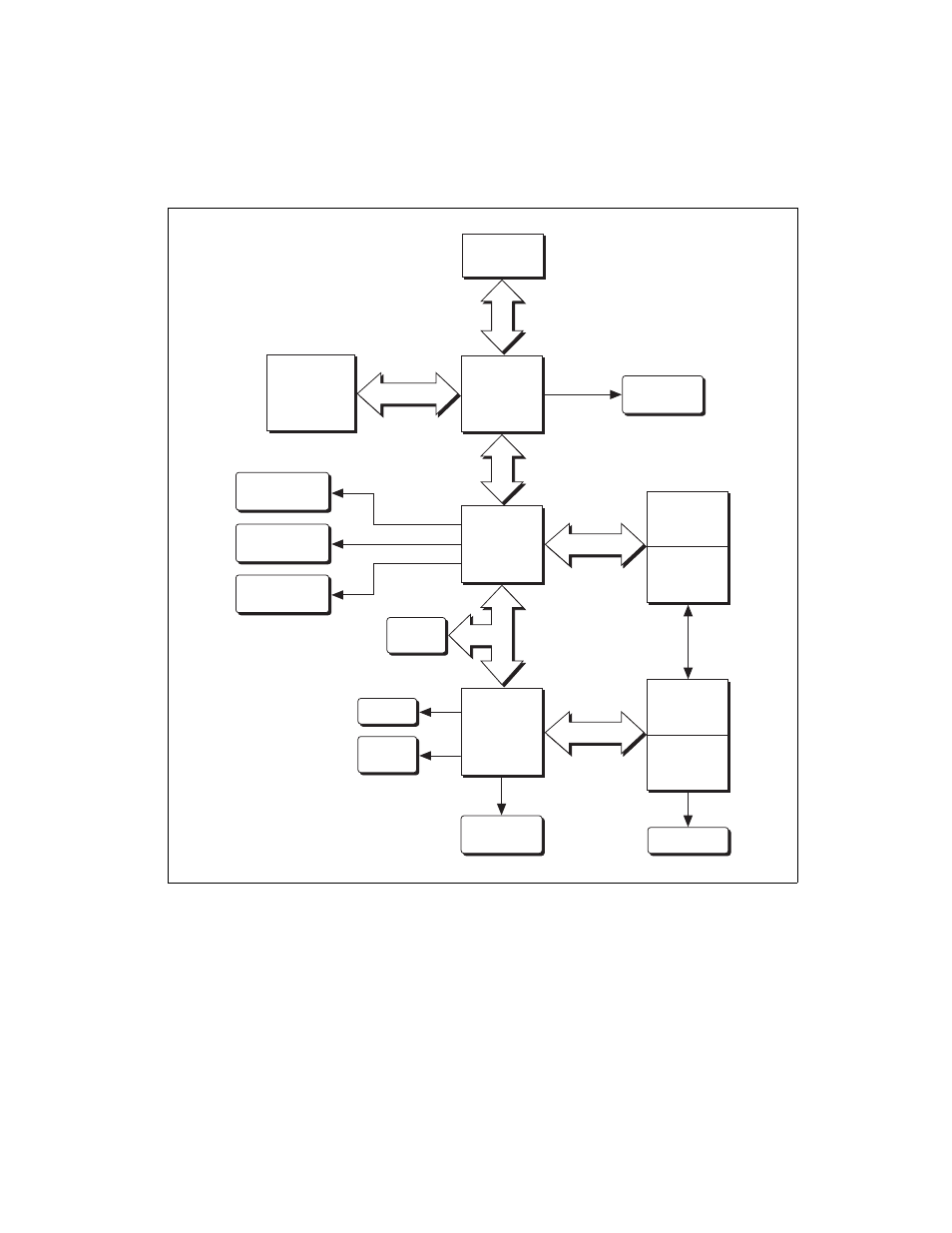
Figure 1-1. NI PXI-8184/8185 Block Diagram
PXI
Connector
Flash
ROM
ATA 100
IDE Interface
SO-DIMM
SDRAM
PC 100
Chip Set
Graphics
Memory
Controller
Hub
VGA
Connector
Socket 370
CPU
Keyboard/
Mouse
Super I/O
COM 1
COM 2
LPT 1
Chip Set
I/O
Controller
Hub
PXI
Triggers
2 USB
Connectors
10/100BaseT
Ethernet
SMB to
PXI Trigger
Watchdog
SMB
Hub Interface
LPC Bus
PS/2
PCI Bus
PCI Bus
This manual is related to the following products: