Names of parts – PLUS Vision M-5 User Manual
Page 7
7
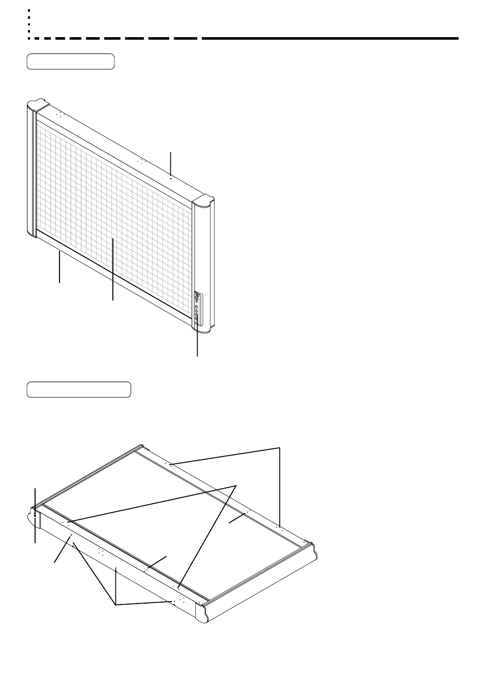
Names of Parts
Front and top
Back and bottom
This diagram shows the copyboard set with the front
side facing down.
1
. Copyboard
2
. Sheet
3
. Control panel
(see page 20)
4
. DC input jack
(see page 20)
5
. USB connector (type B)
(see page 20)
6
. Screw holes for mounting the marker tray
7
. Screw holes for mounting the wall mount fittings
(for upper brackets)
8
. Screw holes for mounting the wall mount fittings
(for brackets)
9
. Screw holes for installing the stand horizontaly
(for upper brackets)
10
. Screw holes for installing the stand horizontaly
(for lower brackets)
11
. Screw holes for installing the stand vertically
(for upper brackets)
12
. Screw holes for installing the stand vertically
(for lower brackets)
12
1
2
3
7, 9
8, 10
6
5
4
12
11
11