Installation procedures, Pico macom inc – Pico Macom CAM-35UNIV User Manual
Page 6
PICO MACOM INC.
12500 Foothill Blvd., Lakeview Terrace, CA 91342 • (818) 897-0028 • (800) 421-6511 • FAX (818) 834-7197
I N S T A L L A T I O N
Installation Procedures
5
1. Electrical Connection:
Plug the power cord into 120 Vac, 60Hz electrical
outlet.
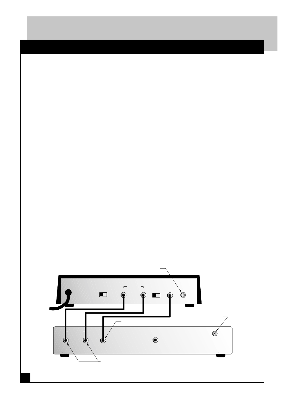
2. Video and Audio Input Connections:
a. Slide the rear display switch to the ON
position. This switch activates and deactivates
the digital display and the channel selector but-
tons on the front panel.
b. Connect in the audio and video plugs from
the input source to the AUDIO in and VIDEO in
jacks respectivily. For sources with only one
audio output, connect to either the right or left
jack.
c. Using the two front panel controls, select a
channel between 14 and 69 for off-air or 37 to
125 for CATV. NOTE: The modulator's LED
displays either off-air UHF or cable (CATV)
channels.
d. After selecting the channel, slide the rear
display switch, on rear panel, to the OFF posi-
tion. This will disable the front panel tuning
controls and turn off the LED display. The
channel you have selected will be stored in
memory.
3. RF Output Connections:
The CAM-35UNIVan be used for various
applications to modulate a signal source such
as a satellite receiver, VCR, laser disk player,
camcorder or surveillance camera to an
ultraband CATV channel or a standard UHF
channel.
4. Channel Selection Guidelines:
a. The CAM-35UNIV modulator converts your
input source to either UHF or Cable (CATV)
channels. Be sure your television set is tuned
properly for off-air or cable reception.
b. Do not select channels that are adjacent to a
CATV or an active off-air channel. In applica-
tions using multiple modulators, do not set mod-
ulators to adjacent channels, for example 20, 21,
22.
c. Do not select a channel on which a local TV
channel is being broadcast.
d. Caution: The lowest UHF frequencies, chan-
nels 14-19, have also been assigned as a commer-
cial communications band. A nearby transmit-
ter could cause intermittent interference on these
channels.
5. Completion:
Once connections have been make and the de-
sired channel has been selected, installation of
the CAM-35UNIV is complete.
Note: If mono receiver is used, audio may be
connected to either audio jack on CAM-35UNIV
VIDEO
IN
AUDIO IN
RF
OUT
DISPLAY
OFF ON
R
L/B.B.
VIDEO
OUT
AUDIO OUT
R
L
LNB
IN
AC120V
60Hz
15W
L B.B.
COMPOSITE
VIDEO OUT
SATELLITE RECEIVER
CAM-35UNIV
FROM LNB
TO DISTRIBUTION SYSTEM
LEFT , RIGHT AUDIO OUT
VIDEO OUT