Smith Cast Iron Boilers Series 28A User Manual
Page 27
Page 27
SERIES 28A BOILER INSTALLATION AND OPERATION INSTRUCTIONS
ns
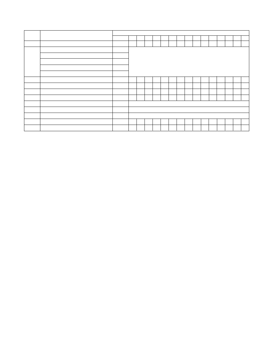
Rear Observation Port Hardware
71301
1
1
1
1
1
1
1
1
1
1
1
1
1
1
1
Burner Mounting Plate Assembly, 9"
70641
Burner Mounting Plate Assembly, 10 1/4"
70640
34
(3)
Burner Mounting Plate Assembly, 12 1/2"
70510
Burner mounting plate determined by burner selection
Burner Mounting Plate Assembly, 10 1/4"
70672
Burner Mounting Plate Assembly, 7 3/4"
70669
ns
Burner Mounting Plate Hardware
71267
1
1
1
1
1
1
1
1
1
1
1
1
1
1
1
35
Burner Mounting Plate Insulating Block
69645
1
1
1
1
1
1
1
1
1
1
1
1
1
1
1
36
Burner Mounting Plate Rope Seal, 3/8 x 7 ft.
76540
1
1
1
1
1
1
1
1
1
1
1
1
1
1
1
ns
Burner Mtg. Plate Ins. Block Hardware
71268
1
1
1
1
1
1
1
1
1
1
1
1
1
1
1
37
Operating Control, PA404A
50493
One per steam boiler
38
3 1/2" Steam Gage
60269
One per steam boiler
39
Hi Limit Control, L404C
50494
One per steam boiler
n/s
Can of Spray Adhesive
70492
1
1
1
1
1
1
2
2
2
2
2
2
2
2
2
n/s
Flue Brush
60090
1
1
1
1
1
1
1
1
1
1
1
1
1
1
1
Ref #
Name of Part
Part #
4
5
6
7
8
9
10
11
12
13
14
15
16
17
18
Number of Sections with Item Quantities Below
(3)
Burner mounting plate assembly includes the burner mounting plate with the observation glass and cover.