IBM X32 User Manual
Page 94
3
2
2
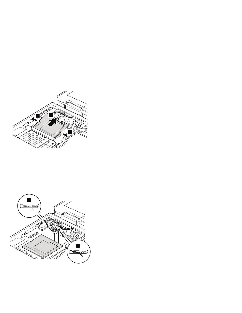
Antenna
cables
4a
and
4b
in
the
following
illustration
are
for
the
wireless
LAN
feature.
Note:
In
step
4a
and
4b ,
if
the
antenna
jack
has
a
tab
marked
“MAIN”
or
“AUX”,
unplug
the
jack
by
pulling
the
tab
with
your
fingers.
If
the
antenna
jack
does
not
have
the
tab,
unplug
the
jack
by
using
the
removal
tool
antenna
RF
connector
(P/N:
08K7159)
or
pick
the
connector
with
your
fingers
and
gently
unplug
it
in
direction
of
the
arrow.
4b
4a
When
installing:
v
Plug
the
gray
antenna
cable
into
jack
J1,
or
MAIN,
or
M,
and
the
black
antenna
cable
into
jack
J2,
or
AUX,
or
A.
v
With
the
notched
end
of
the
card
toward
the
socket,
insert
the
card
into
the
socket,
and
then
press
it
firmly.
Removing
and
replacing
a
FRU
90
MT
2672,
2673,
2884,
2885