Intel EPS1U User Manual
Page 18
SSI
EPS1U Power Supply Design Guide, V1.1
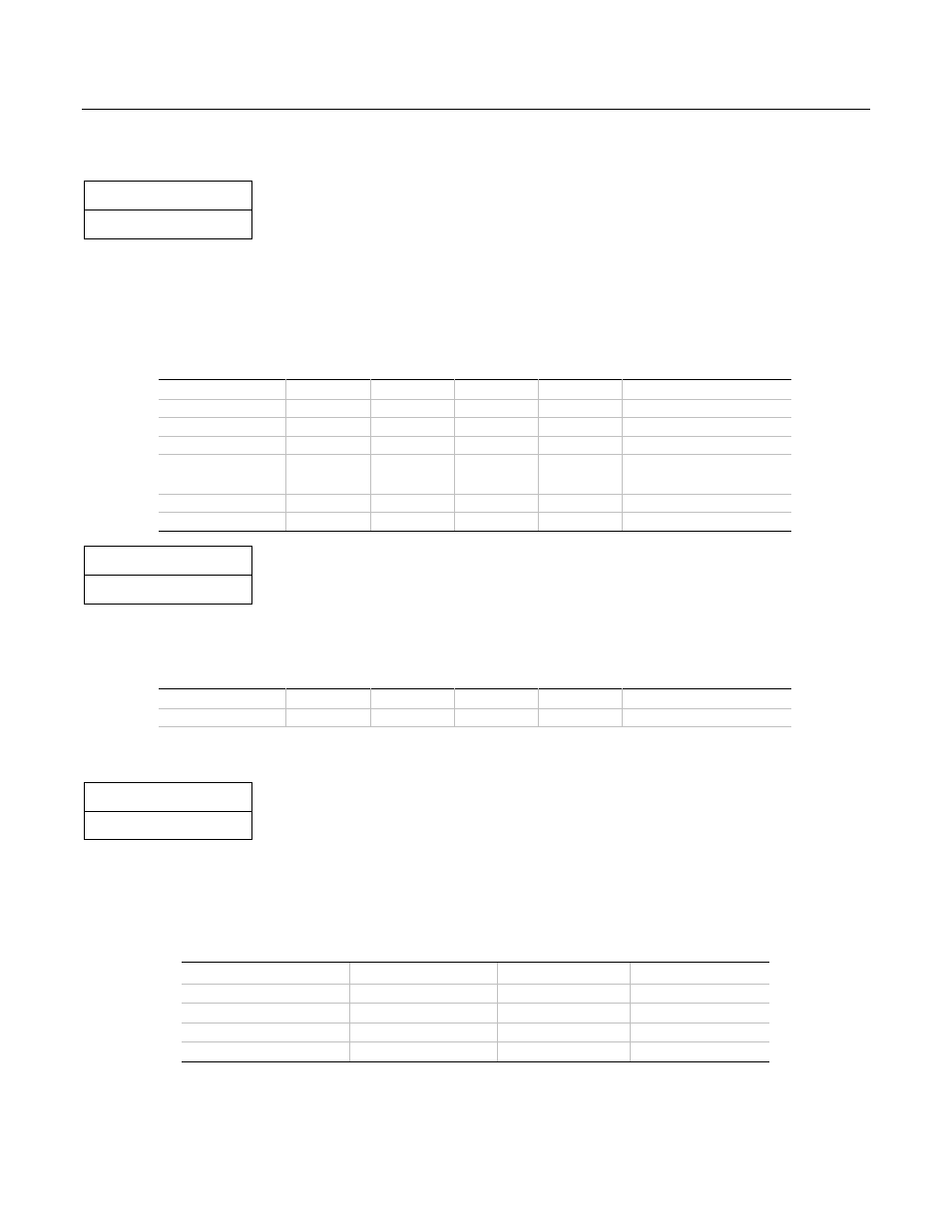
6.5 Voltage Regulation
STATUS
Required
The power supply output voltages must stay within the following voltage limits when operating at steady state and
dynamic loading conditions. These limits include the peak-peak ripple/noise specified in Section 6.8. All outputs
are measured with reference to the return remote sense (ReturnS) signal. The 5 V, 12 V1, 12 V2, –12 V and 5
VSB outputs are measured at the power supply connectors referenced to ReturnS. The +3.3 V is measured at its
remote sense signal (3.3 VS) located at the signal connector.
Table 10: Voltage Regulation Limits
Parameter
MIN
NOM
MAX
Units
Tolerance
+3.3 V
+3.20
+3.30
+3.46
V
rms
+5/-3%
+5 V
+4.80
+5.00
+5.25
V
rms
+5/-4%
+12 V1
+11.52
+12.00
+12.60
V
rms
+5/-4%
+12 V2
+11.52
+12.00
+12.60
V
rms
+5/-4%
-12 V
-11.40
-12.20
-13.08
V
rms
+9/-5%
+5 VSB
+4.85
+5.00
+5.25
V
rms
+5/-4%
STATUS
Optional
Some system applications may require tighter regulation limits on the +5 V output. The optional regulation limits
are shown below.
Table 11: Optional +5V Regulation Limits
Parameter
MIN
NOM
MAX
Units
Tolerance
+5 V
+4.85
+5.00
+5.25
V
rms
+5/-3%
6.6 Dynamic Loading
STATUS
Required
The output voltages shall remain within the limits specified in Table 10 for the step loading and within the limits
specified in Table 12 for the capacitive loading. The load transient repetition rate shall be tested between 50 Hz
and 5 kHz at duty cycles ranging from 10%-90%. The load transient repetition rate is only a test specification.
The
∆
step load may occur anywhere within the MIN load to the MAX load shown in Table 8 and Table 9.
Table 12: Transient Load Requirements
Output
∆ Step Load Size Load Slew Rate Capacitive Load
+3.3 V
30% of max load
0.5 A/
µ
s
100
µ
F
+5 V
30% of max load
0.5 A/
µ
s
100
µ
F
12 V1+(12 V2)
65% of max load
0.5 A/
µ
s
1,000
µ
F
+5 VSB
25% of max load
0.5 A/
µ
s
1
µ
F