Using the rotary data switch and, Switches, Configuration – Mars CASHFLOW 126 User Manual
Page 20: Rotary data switch, Configuration teach switches, Diagnostic led
Using the Rotary Data Switch and
Configuration
Switches
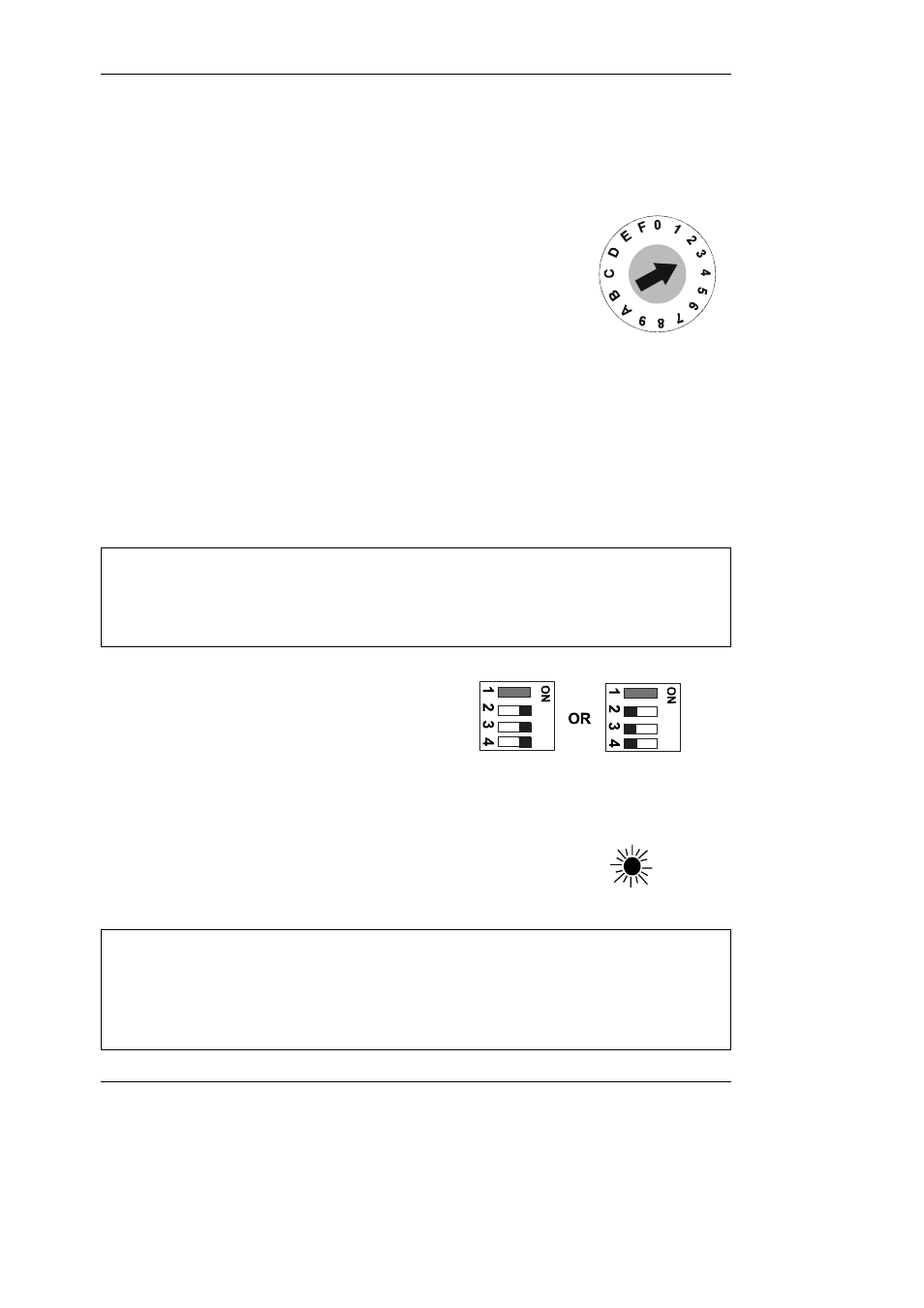
Rotary Data Switch
The rotary data switch is used in conjunction with the
configuration switches. By pointing the arrow in the middle of
the switch, using a fine screwdriver, data can be entered into
the product. In Normal Operation mode the position of the arrow
is not critical to correct operation.
Configuration Teach Switches
These switches can be set to a series of positions which enable the product configuration
to be changed.
When teach modes are to be entered first SWITCH POWER OFF to
the unit, or an un-intended action could be set.
The example given here, with both the rotary data switch and the
configuration switch settings, is to enable channel 3 in the coin set.
+ Wherever in the examples that follow the switch is shown as hatched grey (usually switch 1) it
indicates that it does not matter if the switch is in the ON or OFF position. Switch 1 only features
in the settings for Alarm Enable when it must be in the ON position. When it is in the OFF
position the Alarm function is NOT active.
q
After making any changes the
configuration switches 2, 3, and 4
MUST always return to either of the
Normal Operation positions shown
here.
Diagnostic LED
q
The LED will illuminate to indicate that the product is
powered up, and in addition will give various sequences of
flashes to confirm the acceptance or rejection status of
coins/tokens.
+
Flash Sequence
:Constantly ON Validator Power On
1 Flash
Coin accepted / Reject lever pressed
2 Flashes
Coin not recognised and rejected
3 Flashes
Coin rejected by validator 4th sensor.
4 Flashes
Coin recognised but not accepted due to inhibit setting
16
©, Mars, Inc., 1998
CashFlow
®
126 and CashFlow
®
129 selectors User Guide