Configuration, Validator interface connector – Mars CASHFLOW 126 User Manual
Page 16
CONFIGURATION
Validator Interface Connector
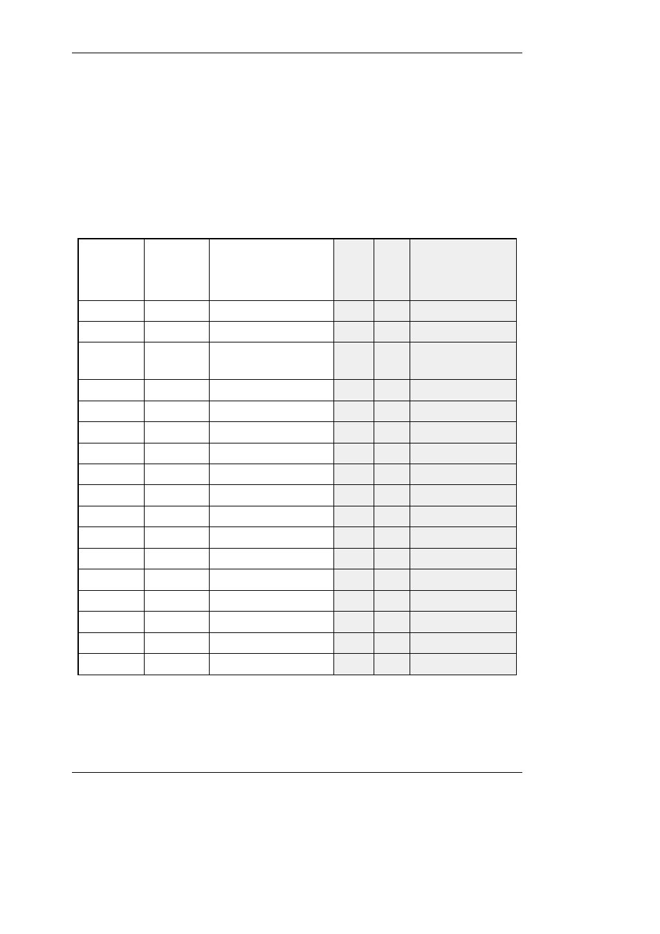
The interface to the validator from the machine is exactly the same as those which apply
to the MS/ME series validators, with the exception of pin 8 of the 17-way connector
Connector 1 can accept either 15 pin or 17 pin interface connectors.
Inhibit 6
17
I
A Coin Inhibit
-
17
Inhibit 5
16
I
B Coin Inhibit
15
16
Inhibit 1
15
I
F Coin Inhibit
14
15
Inhibit 2
14
I
E Coin Inhibit
13
14
Inhibit 3
13
I
D Coin Inhibit
12
13
0V Supply
12
I
0V Supply
11
12
+12V Supply
11
I
+12V Supply
10
11
Inhibit 4
10
I
C Coin Inhibit
9
10
Accept Output 4
9
O
C Coin Output
8
9
Select Line
8
I
Output Mode Input
7
8
Accept Output 3
7
O
D Coin Output
6
7
Accept Output 2
6
O
E Coin Output
5
6
Polarising Key
5
-
Polarising Key 1
4
5
Accept Output 1
4
O
F Coin Output
3
4
Accept Output
Common
3
I
Coin Output
Common
2
3
Accept Output 5
2
O
B Coin Output
1
2
Ident signal
1
O
A Coin Output
-
1
Function
BACTA
Standard
Definition
PIN
No.
Input
or
Outpu
t
Function
Mars Compatible
Definitions
15
Way
Connector
17
Way
Connector
12
©, Mars, Inc., 1998
CashFlow
®
126 and CashFlow
®
129 selectors User Guide