34 siemens plc . 3, Siemens plc • 3 -96, Siemens plc • 3 – Fujitronic Programmable Operation Display UG520H-x User Manual
Page 165: S5 pg port)
2 - 96
34
SIEMENS PLC • 3
(S5 PG Port)
Connection
Connect to the S5 series PG port. The communication parameter setting of POD is done automatically.
Available PLC
*
When useing [6ES5 734-1BD20] cable made by SIEMENS , connect the cable of [ Wiring
Diagram 1 ] to the D-sub 25 pin side of [6ES5 734-1BD20] to communicate with POD.
Available Memory
The assigned memory is indicated while editing the screen as illustrated:
Set the memory to the extent of the memory range of each
PLC model.
Use TYPE number to assign indirect memory for macro programs.
Block No.
Address No.
PLC
Select PLC Type
S5 PG Port
Programing port
on a CPU unit
[6ES5 734-1BD20] cable made by SIEMENS
+RS-232C [Wiring Diagram 1]
S5 series
Wiring Diagram
Link Unit
*
33 SIEMENS PLC
•
3
Memory
TYPE
Remarks
DB
(data register)
0
Use memories more than DB3.
I
(input relay)
1
IW as word device
Q
(output relay)
2
QW as word device
F
(internal relay)
3
FW as word device
T
(timer/current value)
4
C
(counter/current value)
5
AS
(absolute address)
6
Wiring
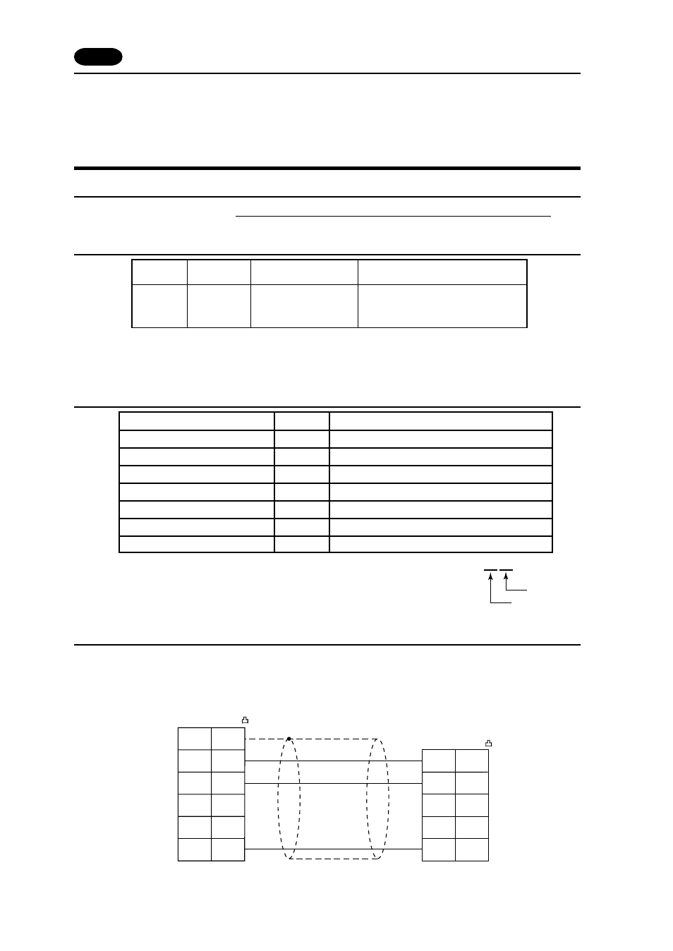
The following is a diagram to show the wiring of the cable which connects POD to PLC.
RS-232C
Wiring Diagram 1
FG
SD
RD
RS
CS
TXD
PC-Converter cable
(6ES5 734-1BD20)
RXD
DTR
2
3
4
SG
2
1
3
4
5
7
GND
5
CTS
7
D-sub 25pin (Male: )
D-sub 25pin (Male: )
*
Use twist shielded cables.
POD (CN1)