Operation – Honeywell 272630D User Manual
Page 2
272630D POSITION FEEDBACK AND AUXILIARY SWITCH ACCESSORY
Automation and Control Solutions
Honeywell International Inc.
1985 Douglas Drive North
Golden Valley, MN 55422
Honeywell Limited-Honeywell Limitée
35 Dynamic Drive
Toronto, Ontario M1V 4Z9
customer.honeywell.com
® U.S. Registered Trademark
© 2010 Honeywell International Inc.
95C-10941—02 T.D. Rev. 08-10
Printed in U.S.A.
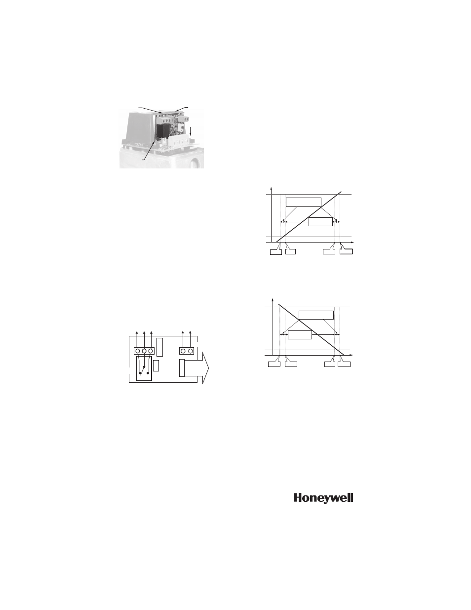
Fig. 1. Installation of auxiliary board.
OPERATION
The first time the valve is powered, the microprocessor
will automatically cycle the valve through a full stroke to
calibrate its position. Any stroke between 1/2" (13 mm)
and 1" (25 mm) will be divided into 30 equal steps. Run
time will be proportional to stroke length. (For example:
nominal timing for 3/4" stroke is 63 seconds. For 1/2"
stroke this would be 42 seconds). The LED lights up
when terminals T5-T6 are powered, and flash when the
actuator is in motion.
NOTE: 272630D requires that the actuator be continu-
ously powered, so ML6984 must be wired in "5-
wire" configuration.
Fig. 2. Wiring and operation of auxiliary board
272630D.
The 272630D provides:
1. A 2-10 Vdc voltage proportional to the valve stem
position. This output is capable of sourcing up to
20 mA dc drive current.
2. An isolated "Form C" relay contact closure that
energizes when the valve is open more than the
setting of the trimmer potentiometer ("trim pot").
Position feedback voltage mirrors the control signal. For
ML6984 and direct acting ML7984 operation, see Fig. 3.
For reverse acting ML7984, see Fig. 4.
Fig. 3. Feedback voltage response for ML6984 and
direct acting ML7984.
Fig. 4. Feedback voltage response for reverse acting
ML7984.
Auxiliary Switch Setup
1. Drive actuator to desired position.
2. Adjust trimmer potentiometer ("trim pot") until relay
is energized. (On-board LED will light).
BRIDGE
SLOTS
1. INSTALL
CIRCUIT
BOARD
FINGERS
M32264
TRIM POT
J1
LED
+FB
NC
RLY1
-COM
C-NC CONTACT
CLOSED
WHEN VALVE
POSITION IS
BELOW TRIM POT
SETTING (DIRECT
ACTING).
C-NO CONTACT
CLOSED
WHEN VALVE
POSITION IS
ABOVE TRIM
POT SETTING
(DIRECT ACTING).
2-10 V,
(4-20 MA
INTO
500 Ω)
FEEDBACK
OUTPUT COM
CONNECT TO MAIN
BOARD FOR POSITION
FEEDBACK.
C NO
M32265
1.75V
2.5V
9.5V
10.25V
FEEDBACK VOLTAGE
LOWER
SEAT
UPPER
SEAT
STROKE
28 STEPS @
0.25V PER STEP
FIRST AND LAST STEPS
ARE @ 0.75V PER STEP
M32266
10.25V
9.5V
2.5V
1.75V
FEEDBACK VOLTAGE
LOWER
SEAT
UPPER
SEAT
STROKE
28 STEPS @
0.25V PER STEP
FIRST AND LAST STEPS
ARE @ 0.75V PER STEP
M32267