Superior valve company, Table 25. type f filter, Table 26. type df (for clean-up) – Heatcraft Refrigeration Products H-IM-72A User Manual
Page 30: Alco controls, Table 27. type af filter, Table 28. type afd (for clean-up), Head pressure control, Valve functions
30
Superior Valve Company
Replaceable Suction Filter
• On many parallel systems, the Superior Valve Co.
suction filter is installed.
Table 25. Type F Filter
Replaceable Cartridges
Shell
Catalog
IBCA
Cartridge
Filter
No.
No.
No.
OD (in)
Area (in
2
)
2CFA
F25A
51071
1 - 23/32
66
3CFA
F35A
51072
2 - 5/8
115
4CFA
F45A
51073
3 - 17/32
189
5CFA
F55A
51074
4 - 1/16
270
Table 26. Type DF (for cleanup)
Replaceable Cartridges
Shell No.
Catalog
IBCA
Cartridge
Filter
No.
No.
No.
OD (in)
Area (in
2
)
2CFA
DF25A
51053
1 - 23/32
66
3CFA
DF35A
51059
2 - 5/8
115
4CFA
DF45A
51060
3 - 17/32
189
5CFA
DF55A
51061
4 - 1/16
270
Alco Controls
Alco Suction Filter
Comparable to the Superior suction filters and
interchangeable cores.
Table
27. Type AF Filter
Replaceable Cartridges -
Shell
Filter
Cartridge
Filter Area
No.
Core
OD (in)
Area (in
2
)
BTAS-2
A2F
1 - 29/32
66
BTAS-3
A3F
2 - 3/4
115
BTAS-4
A4F
3 - 3/4
189
BTAS-5
A5F
4 - 5/16
270
Table
28. Type AFD (for cleanup)
Replaceable Cartridges -
Shell
Filter
Cartridge
Filter Area
No.
Core
OD (in)
Area (in
2
)
BTAS-2
A2F-D
1 - 29/32
66
BTAS-3
A2F-D
2 - 3/4
115
BTAS-4
A2F-D
3 - 3/4
189
BTAS-5
A2F-D
4 - 5/16
270
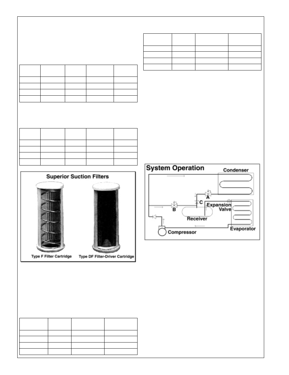
Head Pressure Control
In a system with variable pressure control the receiver
pressure is maintained at the desired pressure by supplying
discharge gas to it through an adjustable outlet regulator.
Further power savings may be realized by directing only the
hot gas to the top of the receiver to minimize the mixing of
cold liquid and hot gas. As a result subcooled liquid is fed to
the evaporators resulting in increased refrigeration effect and
efficiency. Also, the amount of hot gas, that would otherwise
condense to wary liquid, is reduced and a lower cost, smaller
regulator can be used. In general, only one third of bypass is
needed compared to mixing the gas and liquid entering the
receiver.
Valve Functions
Referring to the Figure above, Valve A is an Inlet Pressure
Regulator in the liquid drain line from the condenser, and
senses the condenser pressure. The regulator closes as the
condenser pressure drops below the set point, thus back-
flooding the condenser and reducing the inside surface area
available for condensing.
Valve B is and Outlet Pressure Regulator in the bypass line
from compressor discharge to the condenser liquid drain line.
This valve senses the receiver pressure and opens when this
pressure drops below the set point, thus maintaining the
receiver pressure.
Valve C is an In-line Check Valve in the liquid drain line to
prevent higher pressure from backing up into the condenser
during low ambient conditions when the compressor is idle.