Dimensions and clearances, Flooring, Preparation – Hotpoint RA724 User Manual
Page 14: Tools you will need, Preparation tools you will need, Tools you will need materials you may need, Parts included, Remove shipping materials, 1prepare the opening, Wall mounted
Installation Instructions
PREPARE TO INSTALL THE RANGE
TOOLS YOU WILL NEED
MATERIALS YOU MAY NEED
3-Wire Cord
4‘ Long
4-Wire Cord OR
4‘ Long
(UL Approved 40 AMP)
Adjustable Wrench
Level
1/4” Nut Driver
Phillips Screwdriver
Drill with 1/8” Bit
Pencil
Safety Glasses
Tape Measure
Pliers
Flat-blade
Screwdriver
PARTS INCLUDED
Anti-Tip Bracket Kit
REMOVE SHIPPING MATERIALS
Remove packaging materials. Failure to
remove packaging materials could result
in damage to the appliance.
1
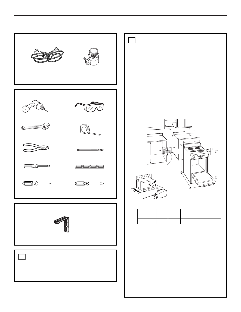
PREPARE THE OPENING
•
Allow 2
″ spacing from the range to adjacent
vertical walls above the cooktop surface. Allow
30
″ minimum clearance between the surface
units and the bottom of unprotected wood or
metal top cabinet, and 15
″ minimum between
the countertop and adjacent cabinet bottom.
•
To eliminate the risk of burns or fire when
reaching over hot surface elements, cabinet
storage space above the cooktop should be
avoided. If cabinet storage space is to be
provided above the cooktop, the risk can be
reduced by installing a range hood that
protrudes at least 5
″ beyond the front of the
cabinets. Cabinets installed above a cooktop
may be no deeper than 13
″.
Flooring under the range
Your range, like many other household items,
is heavy and can settle into soft floor coverings
such as cushioned vinyl or carpeting.
When moving the range on this type of
flooring, it should be installed on a 1/4
″
thick sheet of plywood (or similar material)
as follows:
When the floor covering ends at the front
of the range, the area that the range will
rest on should be built up with plywood
to the same level or higher than the floor
covering. This will allow the range to be
moved for cleaning or servicing.
2
Squeeze Connector
(For Conduit
Installations Only)
B
A
C
From
combustible
walls above
cooking
surface
either side
Models
A
B
C
D
20
″ Wide
20
″
20
3
⁄
8
″
2
″
41
″
24
″ Wide
24
″
24
3
⁄
8
″
2
″
41
″
36
″
D (depth
with door
open)
40
1
⁄
2
″
height
5
″
30
″ min.
15
″ min.
13
″
max.
36
″ max.
14
2
1
⁄
2
″
Wall Mounted
2
1
⁄
4
″
Floor
Cord
Outlet box
Wall
2
″
Recommended acceptable electrical outlet
area. Orient the electrical receptacle so
the length is parallel to the floor.
Surface
mount
outlet