Heath Zenith Utilitech UT-5681-BZ User Manual
Page 2
598-1350-01
2
This fi xture can be directly wall mounted or wall mounted using a
weatherproof junction box. Use the instructions below that apply
to your application.
Installation Without A Junction Box
1. Select a location on a fl at wall with structurally sound wood
and from 5 to 25 feet (1.5 to 7.6 m) from the ground. The wood
should be at least one inch (25 mm) thick to safely secure the
fi xture.
2. Using the mounting template as a guide, mark the 3 mounting
holes. We suggest drilling 3/16" (4.8 mm) pilot holes for the
lag screws.
3. Install the two bottom lag screws fi rst. Screw in the lag screws
so that there is about 3/8" (9.5 mm) of space under the head.
4. Apply silicone caulk around threaded hole on rear of fi xture.
5. Place the fi xture on these two screws and install the top lag screw.
Tighten the top lag screw fi rst, then tighten the remaining lag
screws.
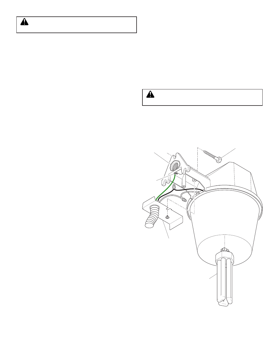
6. Remove the two screws attaching the fi xture cover plate to the
fi xture (see Figure 2).
7. Route the service wires from the conduit through the fi xture
cover plate (see Figure 2).
8. Secure your outdoor cable or fl exible conduit to the cover plate
with a fi tting (not supplied) in accordance with the National
Electrical Code (Canadian Electrical Code in Canada).
Installation Using A Junction Box
1. Thread 1/2" NPT coupler (supplied) into the threaded hole on
the rear of the fi xture.
2. Attach junction box cover plate with 1/2" NPT threads (not
supplied) to coupler.
3. Verify the mounting holes on the cover plate are correctly aligned
with the mounting holes on the junction box and install the 1/2"
NPT nut behind the cover plate. Securely tighten nut against
back of cover plate.
4. Caulk between coupler and cover plate.
5. Remove the two screws attaching the fi xture cover plate to the
fi xture.
6. Route service wires through coupler and into the fi xture.
7. Securely attach the cover plate to the junction box.
CAUTION: Do not use any other wattage lamps
in this fi xture.
To test operation during daylight, cover the photocontrol (round
object on front of fi xture) with black electrical tape. Turn on the
power. The light should come on immediately and will take a few
minutes to reach full brightness. Uncover the photocontrol and your
unit will operate automatically—on at dusk, off at dawn.
Complete The Installation
1. Connect the fi xture wires to the service wires as shown in Figure
2 (black to black and white to white).
2. This
fi xture must be connected to ground. Secure the service
ground wire under the head of the green ground screw (see
Figure 2).
3. Install the cover plate. Secure with the two screws provided (see
Figure 2).
4. Plug in the 42 watt compact fl uorescent lamp provided (NEMA
designation CFTR42W/GX24Q with GX24Q-4 base).
ATTENTION: When removing, grasp bulb by the base. Do not
grasp glass bulb to remove.
Cover Plate
Figure 2
Caulk
Ground
Screw
Bulb
Lag Screw
WARNING: Turn power off at the circuit breaker
or fuse.