Save these instructions, Assembly – Harbor Freight Tools 66242 User Manual
Page 4
Page 4
For technical questions, please call 1-800-444-3353.
SKU 66242
14. Do not exceed 145 PSI air pressure.
15. Maintain labels and nameplates on Bottle Jack.
These carry important safety information.
If unreadable or missing,
contact Harbor Freight Tools for a replacement.
16. Bleed the hydraulic system before its initial use.
17. Do not leave tool unattended when it is
connected to a compressed air supply.
Release tool’s load, and disconnect from
compressed air supply before leaving.
18. This product is not a toy.
Keep it out of reach of children.
19. When lifting only one wheel, make sure to
support load immediately with one jack stand
(not included) placed under side of vehicle being
lifted. Align saddle of jack stand directly under
vehicle’s seam or recommended lifting point.
20. When lifting entire front end or rear end of
vehicle, make sure to support load immediately
with two jack stands. Align saddles of jack
stands directly under vehicle’s frame or
recommended lifting points. Also, make sure
jack stands are adjusted at the same height.
21. Do not use Bottle Jack with the vehicle’s
engine running. When running, the vehicle’s
engine produces carbon monoxide, a colorless,
odorless, toxic fume that, when inhaled,
can cause serious personal injury or death.
22. Keep hands and feet away from all moving
parts of the Bottle Jack when applying or
releasing a load. Keep people and animals at
a safe distance when using the Bottle Jack.
23. Do not allow anyone in vehicle
when using Bottle Jack.
24. Do not use Bottle Jacks to lift both ends
of a vehicle at the same time.
25. Before lowering the Bottle Jack, make sure
tool trays, jack stands, and all other tools and
equipment are removed from under the vehicles.
26. The warnings, precautions, and instructions
discussed in this manual cannot cover all
possible conditions and situations that may occur.
The operator must understand that common sense
and caution are factors, which cannot be built into
this product, but must be supplied by the operator.
SAVE THESE
INSTRUCTIONS
Initial Tool Set Up/Assembly
Read the ENTIRE IMPORTANT
SAFETY INFORMATION section at the
beginning of this manual including
all text under subheadings therein
before set up or use of this product.
Note: For additional information regarding the
parts listed in the following pages, refer to the
Assembly Diagram near the end of this manual.
Note: This air tool may be shipped with a protective plug
covering the air inlet. Remove this plug before set up.
Assembly
1. Assemble the Handle and its 6.x series parts that
come in Box B. See Assembly Diagram on page 10.
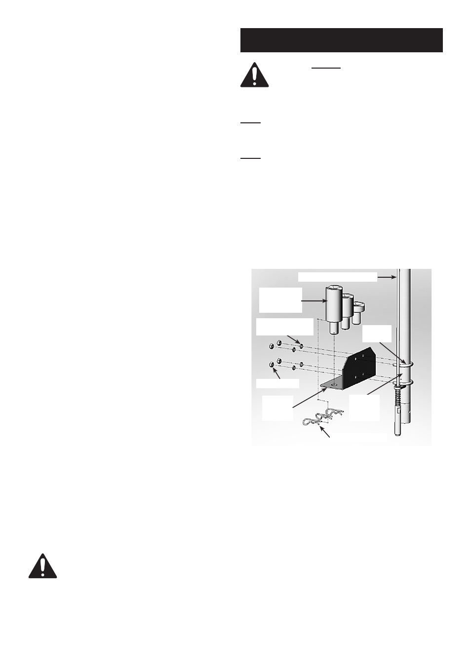
2. Attach Adapter Holder (12.5) to the Outside Tube
(6.1) of the Handle Assembly with two U-Bolts (12.6),
Lock Washers (12.7) and Nuts (12.8).
See Figure 1, below.
Fig. 1
Adjustable Rod (6.3)
Adapters
(12.1, 12.3,
12.4)
U-Bolts
(12.6)
Nuts (12.8)
Adapter
Holder
(12.5)
Spring Washers
(12.7)
Hitch Pin (12.9)
Outside
Tube
(6.1)
3. Tighten Nuts to secure Adapter Holder to Handle.
4. Put height adjustment Adapters into the Adapter
bracket and lock each with a Hitch Pin (12.9).
See Figure 1.