Transmitter specifications, Hubbell – Hubbell Fixed Transmitter 31.350 User Manual
Page 2
JPS-500-1M © 2000
Printed in U.S.A.
HUBBELL
50 Edwards Street
Madison, Ohio 44057
(440) 428-1161
Fax (440) 428-7635
4301 Cheyenne Drive
Archdale, NC 27263
(336) 434-2800
Fax (336) 434-2801
Hubbell Industrial
Controls, Inc.
a subsidiary of
Hubbell Incorporated
Hubbell Industrial Control Solutions
http://www.hubbell-icd.com/radiocontrols/
72 MHz Transmitters
450 MHz Transmitters
Frequency Range
72-76 MHz
406–430, 450–475 MHz
Channel Available
per customer license
per customer license
Frequency Stability -10 to 60
°
C
±
5ppm
±
5ppm
Emission Type
10KOFID
10KOFID
Spurious/Harmonic Output (below carrier)
>70db
>80db
Output to Antenna
300 mW
300 mW
(low)
/ 1 W
(high)
Effective Radiated Power
150 mW
150 mW
(low)
/ 500 mW
(high)
Nominal Range (line of sight)
2000 ft*
2500 ft
(low)
/ 3500 ft
(high)
*
FCC Identifier
LRL922206-72
LRL922206-450
Canada Certificate Number
2259-203-224
2259-203-222
Voltage Requirement
120V ac or 250V dc
120V ac or 250V dc
Battery Usage
no battery
no battery
Recharge Time
no battery
no battery
Operating Temperature
-22
°
F to 140
°
F -30
°
C to 60
°
C
-22
°
F to 140
°
F -30
°
C to 60
°
C
Relative Humidity
20% to 90% non - condensing
20% to 90% non - condensing
LED Indicator
Flashing: transmitting
Flashing: transmitting
Function Lever Switches
as required
as required
Auxiliary Switches
as required
as required
Weight with Battery
No Battery
No Battery
* The use of “Whip Antennas”, raised 20 to 30 feet above ground level, on both transmitter
and receiver, increases the nominal range to 2 miles.
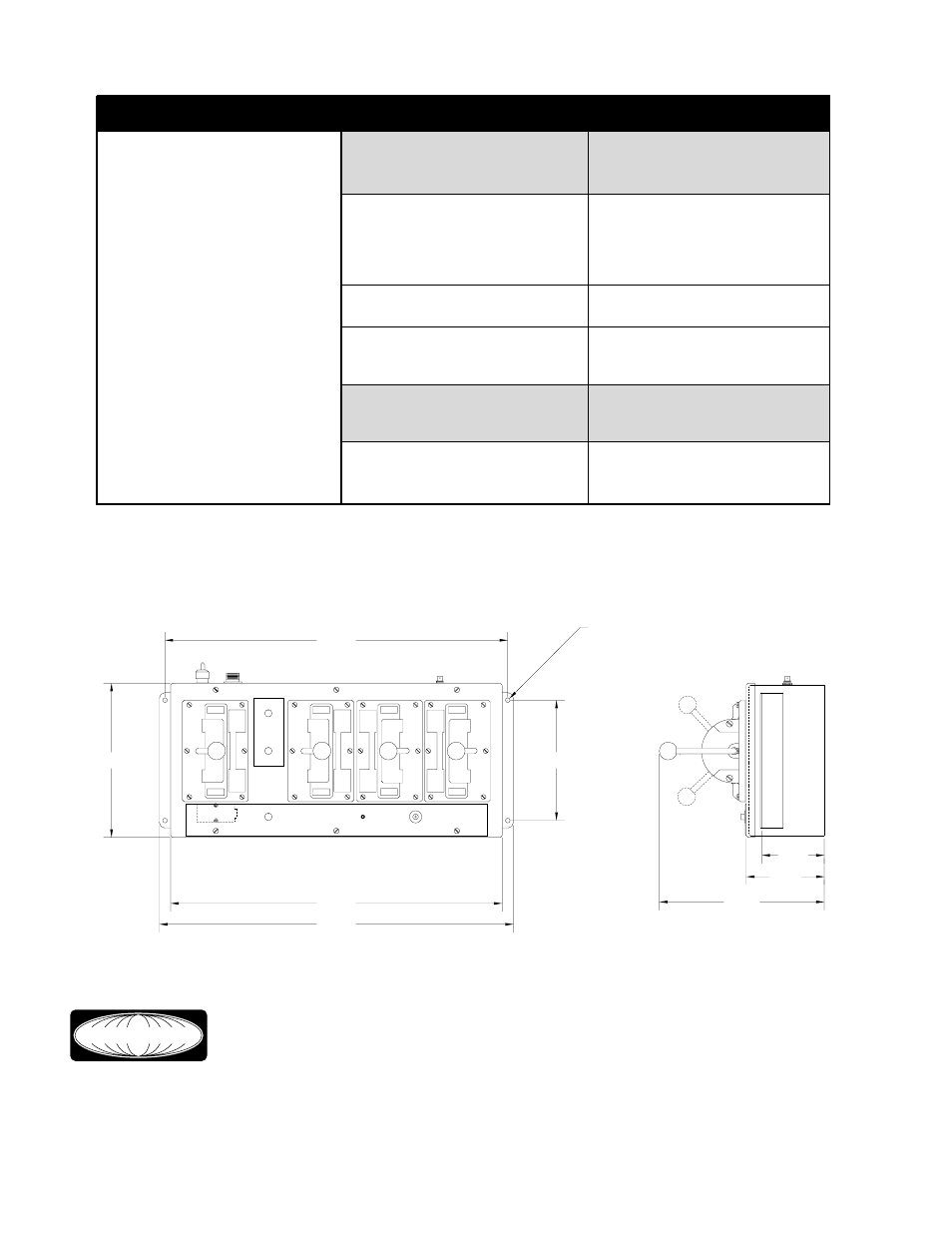
Transmitter Specifications
11.00
5.25
4.15
10.25
23.50
22.00
*
*
*
*
*
*
*
BRAKE
APPLY
RELEASE
E-STOP
RUN
R.F.
HOIST
TROLLEY
BRIDGE
MAGNET
HORN
XMIT
0.31 DIA.
8.00
22.75
UP
DOWN
NORTH
SOUTH
WEST
EAST
LIFT
DROP