Operation – Husqvarna 924SB User Manual
Page 10
10
TO MOVE FORWARD AND BACKWARD (See Fig. 13)
SELF-PROPELLING, forward and reverse movement of
the snow thrower, is controlled by the traction drive control
lever located on the left side handle.
•
Squeeze traction drive control lever to handle to en gage
the drive system.
•
Release traction drive control lever to stop the forward
or reverse movement of the snow thrower.
SPEED and DIRECTION are controlled by the drive speed
control lever.
•
Press downward on the speed control lever and move
lever to de sired po si tion BE FORE engaging the trac -
tion drive control lever. Be sure lever springs back and
locks into desired position.
OPERATION
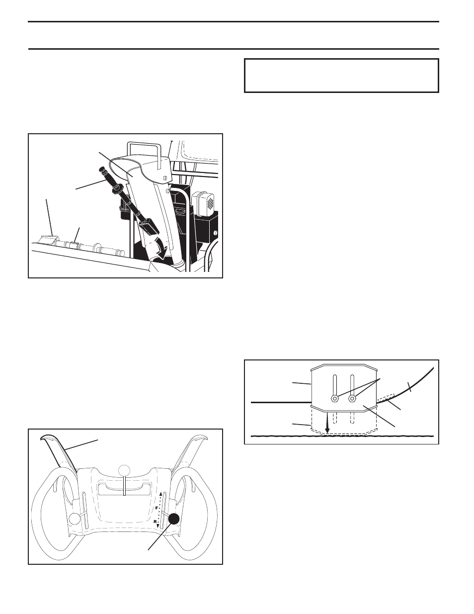
TO ADJUST SKID PLATES (See Fig. 14)
NOTE: The wrench provided in your parts bag may be
used to adjust the skid plates.
Skid plates are located on each side of the auger housing
and adjust the clearance between the scraper bar and the
ground surface. Adjust skid plates evenly to proper height
for current surface conditions. For removal of snow in
normal con di tions, such as a paved driveway or side walk,
place skid plates in the highest position (lowest scraper
clear ance) to give a 1/8" clearance between the scraper
bar and the ground. Use a middle position if the surface
to be cleared is uneven.
NOTE: It is not recommended to operate the snow thrower
over gravel or rocky surfaces. Objects such as gravel, rocks
or other debris, can easily be picked up and thrown by the
impeller, which can cause serious personal injury, property
dam age or damage to the snow thrower.
•
If snow thrower must be operated over gravel surface,
use extra caution and be sure skid plates are adjusted
to lowest (highest scraper clear ance) position.
SCRAPER BAR
The scraper bar is not adjustable, but is reversible. After
con sid er able use it may become worn. When it has worn
almost to the edge of the housing, it can be reversed,
providing additional service before requiring replacement.
Replace a dam aged or worn scrap er bar.
DRIVE SPEED
CONTROL LEVER
TRACTION DRIVE
CONTROL LEVER
FIG. 13
CLEAN-OUT
TOOL
FIG. 12
MOUNTING
CLIP
DISCHARGE CHUTE
SKID PLATE
LOW POSITION
(HIGH GROUND
CLEAR ANCE)
HEX
NUTS
HIGH POSITION
(LOW GROUND
CLEARANCE)
AUGER
HOUSING
FIG. 14
SCRAPER
BAR
1. Shut off engine and wait for all moving parts to stop.
2. Adjust skid plates by loosening the hex nuts, then mov-
ing skid plate to desired position. Be sure both plates
are adjusted evenly. Tighten securely.
After the packed snow has been dislodged, return the clean-
out tool to it's mounting clip by pushing it into the clip.
•
Make sure the discharge chute is pointed in a safe direc-
tion (no vehicles, buildings, people, or other objects are
in the direction of discharge) before restarting engine.
• Restart the engine, then squeeze the auger control
lever to the handle to clear snow from the auger hous-
ing and the discharge chute.
CAUTION: Do not move speed con trol le ver
when traction drive control lever is en gaged.
Damage to the snow thrower can result.
•
Slower speeds are for heavier snow and faster speeds
are for light snow and transporting the snow thrower. It
is recommended that you use a slower speed until you
are familiar with the operation of the snow thrower.