Т³гж 6, Setting environment, Installation – haier Little Sea-ox FCD JTHA40-III(E) User Manual
Page 6: Description of the symbols
5
Setting Environment
² »
Ò ª
° ²
Ч °
У Ъ
О Ю
· ¨
Е Е
Л ®
µ Ä
µ Ø
· ½
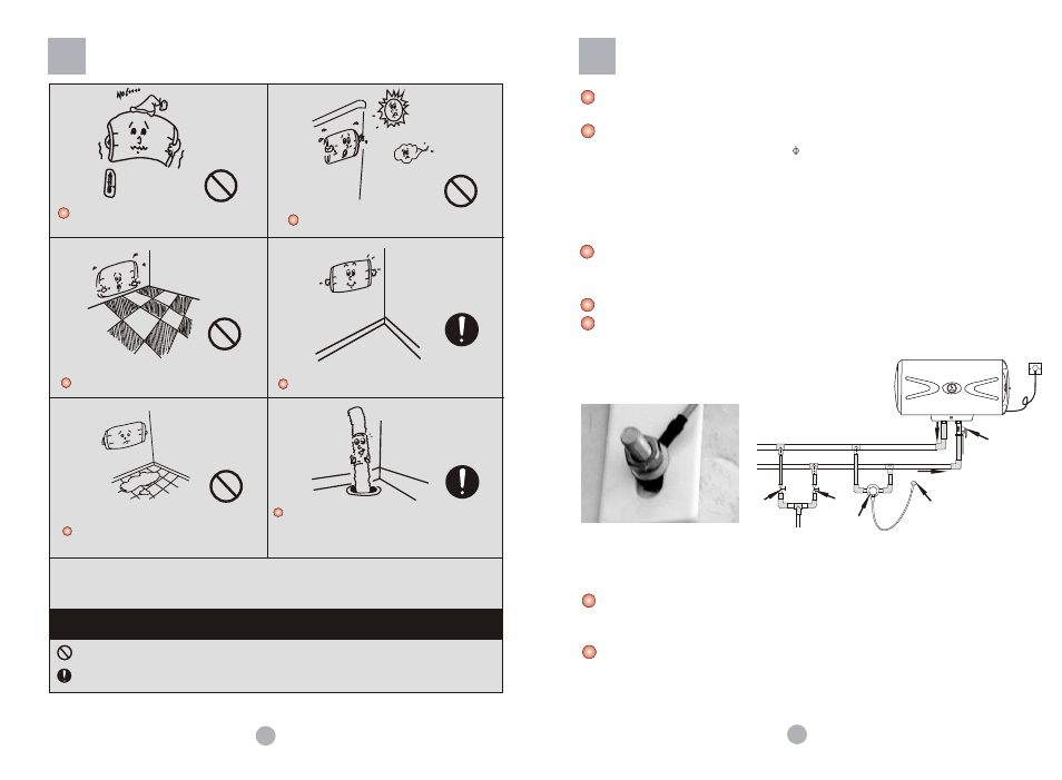
Description of the Symbols
Do not set it at place where is too cold and
may freeze.
Do not set at outdoor places.
Do not use as floorstanding appliance.
Please mount it to firm and reliable wall.
Do not install to places without sewer.
In case connecting water heater with water drain
hose, connect the drain hose to the inlet of the
sewer to avoid polluting by splashing.
The original pipeline of the water heater is an organic part of "Safe Care". Do not remove it by yourself.
Otherwise we will not take responsibility for the injure and loss caused by the safety trouble occurred
therefrom.
Never do that
Be sure to act as per instructions
6
Installation
Connection and use of safety valve:
The safety valve should be connected to the cold water inlet pipe. Please check
carefully if the direction is correct after installation. The correct direction of installation
is that the arrowhead on the safety valve should point to the water heater.
Please connect the drain hose to the safety valve. Connect one end of the hose to the
safety valve vent and the other end to the sewage drain. The hose can be cut short or
extended as necessary. The hose shall be installed as inclined downward.(see to
Figure 4)
(Figure 3) for reference in installation only
Cold water inlet
Mixing valve
Hot water
outlet valve
Cold water
outlet valve
Shower head
Hot
water
outlet
Safety valve
Installation must be made by installers of or designated by our company after-service
department. The water heatershall be wall-mounted.
Before installation, make sure water heater rear wires are fit firmly. Determine an
installation location. Make four holes
12mm, 65 mm deep in the wall with an impact
drill according to installating dimension. Insert fixexpansion hooks and expansion bolts
in corresponding wall holes. Lift the water heater. Insert wall rack onto the hooks and
bolts. Fit flat washers, rear wires and nuts in turn onto the bolts (see Figure 2). Tighten
the nuts and check them firm. Install accessories such as safety valve, drain hose as
shown in Figure 3. Use sealing compound to prevent water leakage.
(Figure 2)
To facilitate installation and removal, it is suggested a G 1/2" movable nut is fitted at
appropriate locations on inlet and outlet pipes respectively. Find water supply location.
Connect inlet pipe, outlet pipe and city water pipe respectively to the use point.
The hot water pipe shall not be too long to reduce the heat losses.
Please reserve some space in installation for the future maintenance.