General instructions, Description and purpose – Husqvarna FS 800 EM User Manual
Page 4
4
The FS800 E/EM floor saw is a professional machine designed
for cutting reinforced concrete, asphalt and stone.
This machine may only be used by those who have carefully
read this instruction manual and follow its instructions.
If you are unsure about any point please consult the supplier
before starting to use the machine.
You must not modify the saw in any way without obtaining
written approval from Husqvarna Construction Products
Sweden AB. Modifications that are not approved could lead
to serious or fatal injury to yourself or others. Husqvarna
Construction Products Sweden AB does not accept any liability
if the machine is used in any way or for any purpose that does
1. Description and purpose
The FS800 E/EM electric floor saw is designed for cutting re-
inforced concrete, asphalt and other stone material in the
building industry.
The saw has a full-width blade shaft, as shown in figure 1.1.2.
This permits a diamond blade to be fitted on either the right of
left side of the machine to allow cutting into corners from
either side. The blade guard can be divided as shown in figure
1.1.5.
The floor saw is equipped with a water-cooling system, as
shown in figure 1.2.2 to ensure effective cooling of the
diamond blade and prevent dust formation.
The FS800 E/EM floor saw has the following controls:
• Height adjustment wheel as shown in figure 1.1.1.
•
Blade shaft as shown in figure 1.1.2.
•
Alignment guide for cutting a straight line as shown in
figure 1.1.4.
•
Adjuster screw for the above, as shown in figure 1.1.3.
•
Blade guard as shown in figure 1.1.5.
•
Control panel with switch, phase inverter and emergency
stop as shown in figure 1.1.8.
•
Power socket as shown in figure 1.2.1.
•
Water-cooling nozzle as shown in figure 1.2.2.
•
Guard for exposed drive shaft as shown in figure 1.2.3.
•
Parking brake as shown in 1.2.4.
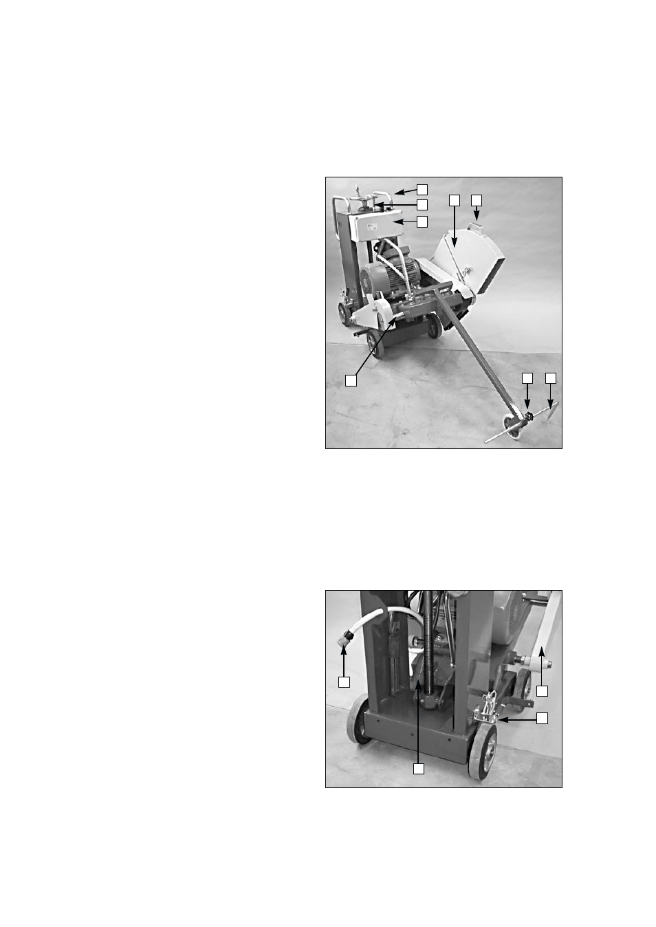
Figure 1.1
1.1.1. Height adjustment wheel
1.1.2. Pulley shaft
1.1.3. Adjuster screw for alignment guide
1.1.4. Alignment guide
1.1.5. Two-piece blade guard
1.1.6. Lifting handle for blade guard
1.1.7. Guide handle
1.1.8. Control panel with switch, phase inverter and emergency
stop
Figure 1.2
1.2.1. Power socket
1.2.2. Water-cooling coupling
1.2.3. Guard for exposed pulley shaft
1.2.4. Parking brake
General instructions
_ _ _ _ _ _ _ _ _ _ _ _ _ _ _ _ _ _ _ _ _ _ _ _ _ _ _ _ _ _ _ _ _ _ _ _ _ _ _ _ _ _ _ _ _ _ _ _ _ _ _ _ _ _ _ _ _ _ _ _ _ _ _ _ _ _ _ _ _ _ _ _ _ _ _ _ _ _ _ _ _ _ _ _ _ _ _ _ _ _ _ _
1
8
6
3
4
2
1
3
4
5
7
2
not comply with these instructions.